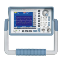
Manual Test Procedure R&S SM300
Version 04 72
Service Manual SM300: 1147.1652.00 Instrument Part No SM300: 1147.1498.03
2.4.2 Interface Test
2.4.2.1 USB Bus Interfaces
Preparation
1.
Install PC Software R&S SM300-K1 on the PC. Connect the USB interface of
the R&S SM300 and the external PC via USB cable.
Test
2.
Run R&S SM300-K1 as described in the operating manual.
Preparation
3.
Connect an appropriate printer or USB Stick to the R&S SM300.
Test
4.
Access this device by the external PC. The device must be accessible.
2.4.3 Reference Frequencies
For adjustment of the internal reference oscillator, synchronization with an
external reference frequency is performed.
Note
The resolution of the frequency counter/analyzer should be max. 1/10 of the
maximum permissible deviation.
2.4.3.1 REF IN
The frequency and level ranges and the pull-in range are checked. The signal
generator and the frequency counter must be synchronized (test setup
1). Set
SM300 to 1 GHz and 0 dBm level.
Preparation
1.
Feed in at REF IN: 10 MHz sinewave, 0.5 V (rms)
Test
2.
The counter should read 1 GHz ± resolution of counter.
Preparation
1.
Feed in at REF IN: 10 000.05 MHz sinewave, 0.5 V(rms)
Test
2.
The counter should read 1 GHz ± resolution of counter.
Preparation
1.
Feed in at REF IN: 9 999.95 MHz sinewave, 2 V(rms).
Test
2.
The counter should read 1 GHz ± resolution of counter.
2.4.3.2 REF OUT
The level and frequency are checked.
Procedure
1. Set the R&S SM300 to internal reference.
2. Measure at REF OUT: 10 MHz ± 20 Hz, voltage >0.5 V(pp).
2.4.3.3 Internal Reference Frequency Adjustment
The internal reference frequency oscillator can only be adjusted by using a
PC and special adjustment software..
Procedure
Refer to Chapter 3 Adjustment of 10 MHz Crystal

 Loading...