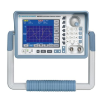
Instrument Assembly for Board and Module Exchange R&S SM300
Version 04 38
Service Manual SM300: 1147.1652.00 Instrument Part No SM300: 1147.1498.03
Figure 1-4 Figure 1-5
Figure 1-6 Figure 1-7
Installing the case
top and bottom
1. Remount upper and lower case (until flush with front panel).
2. Fasten two upper and lower screws (DIN7985 M3×4).
3. Fasten 12 side screws (DIN7985 M3×4).
Installing the rear
frame
1. Push frame into cases until it engages (audible).
2. Fasten 2 screws in side recesses and 2 screws in recesses for power
pack. (DIN7985 M3×8).
3. Fasten 16 or 8 screws for modules (DIN7985 M3×8).
4. Fasten 2 upper and 2 lower screws (DIN7985 M3×5).
5. Install handle (see section
1.3.3.2).
6. Install both protectors (see section
1.3.3.1).
1.3.3.4 Rotary Knob including Finger-Tip Control
Removing the rotary
knob
x Pull off rotary knob (may require using slotted screwdriver or tweezers).
Figure 1-8

 Loading...