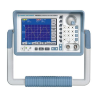
Introduction R&S SM300
Version 04 20
Service Manual SM300: 1147.1652.00 Instrument Part No SM300: 1147.1498.03
1 Service Concept
About this chapter
Chapter 1 describes the service concept, the installation and update of the
software and how to install and remove the spare parts.
More information
Chapter 2 shows a performance test.
Chapter
3 describes the adjustment of a 10 MHz crystal.
Chapter
4 is a functional description.
Chapter
5 provides troubleshooting information.
1.1 Introduction
Smart Instruments
family 300
All measurement instruments of the Smart Instruments family 300 are
based on the same mechanical principle: the instrument case consists of a
closed metal carrier onto which two identical plastic cases are mounted.
The lateral slot between the two plastic cases is used to insert the handle or
to fix the adaptor for rack mounting.
The instruments differ by the printing on the front panel and the front and
rear connectors. All connectors are firmly mounted to the generator module
which is inserted into the instrument from the rear. The control PC and the
power supply are also closed modules which are inserted into the
instrument in a similar way as the generator module.
These three types of modules are interconnected via the backplane which is
located at the front of the modules. The backplane distributes power from
the power supply to the modules and provides access to the USB bus,
which is the internal communication medium in the instruments.
The backplane, the control PC module and the power supply are identical
for all instruments of the family 300 and are available as spare parts. The
generator module itself is also a spare part and can be exchanged in case
of failure. This replacement process eliminates the need of repair on
component level and allows for fast repair cycles.
To ensure correct function of an instrument after module exchange the
modules need to be registered inside the instrument using the Series300
wizard. If the control PC is exchanged, the MMI for an individual instrument
(such as SM300) needs to be downloaded to the module.
The generator module spare part is already calibrated and does not require
recalibration before mounting it into the instrument.
1.2 Installation of Software Updates and Drivers
Please refer also to the latest Release Note for software updates. Release Notes and update files are
stored on the GLORIS firmware/software board.
1.2.1 Installing the Device Drivers
1.2.1.1 Installing Steps for Windows 2000
Connecting R&S
SM300 to the PC
R&S SM300 is connected to the PC via the USB interface. The connection
cable has two plug types. Plug A is connected to the computer (Ê computer
manual) and plug B is connected to the R&S SM300 (Ê R&S SM300
operating manual, Chapter 2.2 Rear View).

 Loading...