Instrument Tour
R&S
®
TSMA6
26Getting Started 4900.8040.02 ─ 07
RF IN Connector
The RF IN connector is the RF input of the R&S TSMA6. The multi-band RF pad-
dle antenna (700 MHz to 2.6 GHz), which is included in the shipment of
R&S TSMA6 or any custom RF source is connected to this SMA connector. The
maximum input power is +20 dBm/10 V DC.
Risk of instrument damage
Do not overload the maximum allowed input of +20 dBm.
Non-compliance destroys the input mixer.
Battery Pack Connector
The battery pack connector is used to connect a battery pack unit (R&S TSMA6-
BP, R&S No. 4900.9001.02) allowing mobile operation.
5.3 Status LEDs
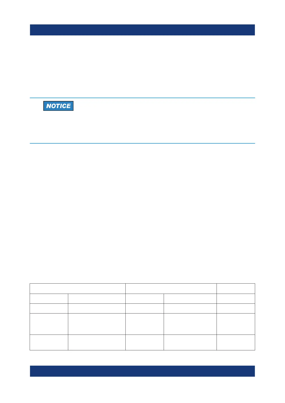
The four LEDs on the rear panel display the following states.
●
[Scanner State / Scanner Pwr]
Indicates the state of the scanner component
●
[Mode]
Indicates the device status
●
[Meas]
Indicates the state of the SW application
Device Scanner
[Mode] LED [Meas] LED [Pwr] LED [State]LED Comment
Off Off Off Off Power Off
green (BLINK-
ING, 1 Hz)
--- --- --- Power On
Selftest /
Power Down
green (CONT.) --- --- --- Power On /
WLAN Off
Status LEDs
 Loading...