33
Wuhan Raycus Fiber Laser Technologies Co., Ltd.
User Guide of RFL-C20000M-CE
6. Laser Wiring Diagram and Operation Steps
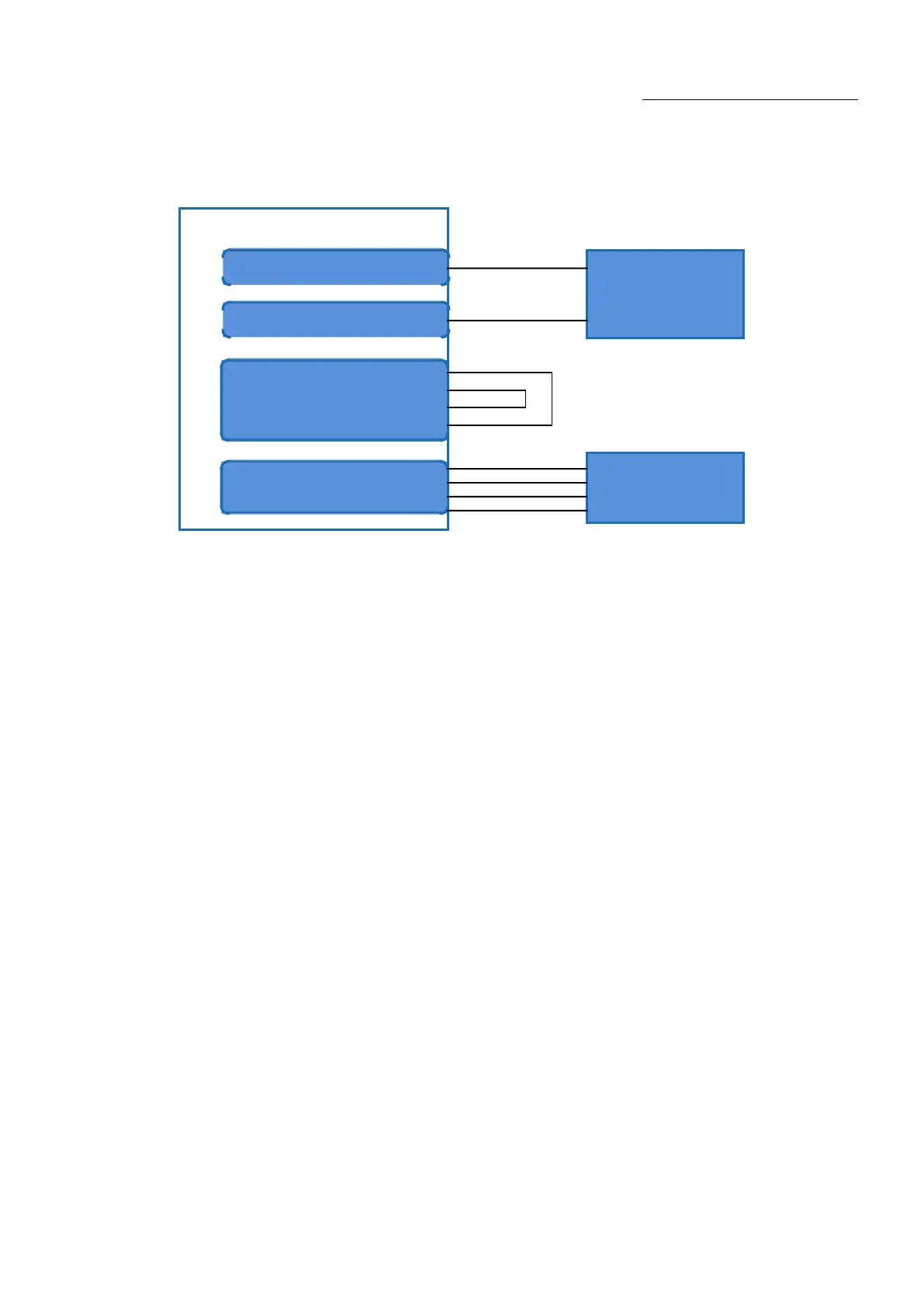
6.1. Internal control in ON Mode
Figure 16software mode wiring diagram whenkey switch at “ON” position
Operations Steps
a) Turn the knob switch on the rear panel to“ON”
b)Turn the key switch to“ON”
c) Open the Raycus Laser Control System
d)Click the guide laser “ON” button to view the guide laser
e) Turn off “AD” mode and turn off external control mode (this mode can be memorized when
power off)
f)Click the main power “ON”
g)Waiting for “Ready”
h)Set laser emission parameters
i) Click the laser “ON”.
Serial port line
Ethernet cable
Interlock1