39
Wuhan Raycus Fiber Laser Technologies Co., Ltd.
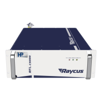
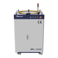
User Guide of RFL-C20000M-CE
Operations Steps:
a) Turn the knob switch on the rear panel to“ON”
b)Turn the key switch to“REM”
c) Short-circuit pin 8/9 on XP2
d)XP1-A1 connects to 24V
e) Connect XP1-A5 to 24V and turn on the guide laser; after checking the optics, connect XP1-A5 to
0V and turn off the guide laser
f)XP1-C1 is connected to 24V, and the main power is turned on (users can also directly press the
“LASER” button, or the host computer software clicks the main power “ON”)
g)Waiting for “Ready”
h)The Raycus Laser Control System sets the power, XP1-A2 is connected to 24V, and the control
board card outputs MOD signal
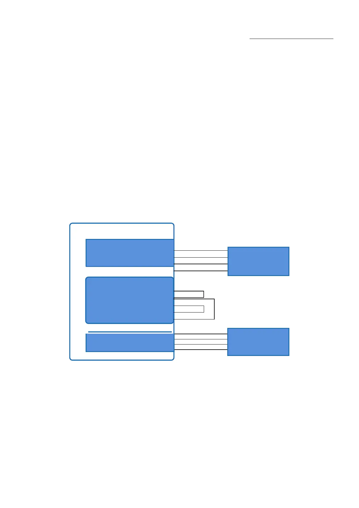
6.7. Programming Mode in REM Mode
Raycus Laser
8
9
17
18
19
20
Figure 23Wiring diagram of programming mode in REM Mode
A1(Laser Request)
A2(Laser EN)
A8~A14(ProgramNum)
A16(COM)