Home
Raycus
Measuring Instruments
RFL-C20000M-CE
Page 50 (Multi-Laser Control Area)
Raycus RFL-C20000M-CE - Multi-Laser Control Area
73 pages
Manual
Save Page as PDF
To Next Page
To Next Page
To Previous Page
To Previous Page
Loading...
46
Wuh
a
n
Ra
yc
us
Fib
e
r
La
se
r
Te
ch
n
o
lo
gi
e
s
Co
.
,
L
td
.
User
Guide
of
RFL-
C
2
0
0
0
0
M
-
CE
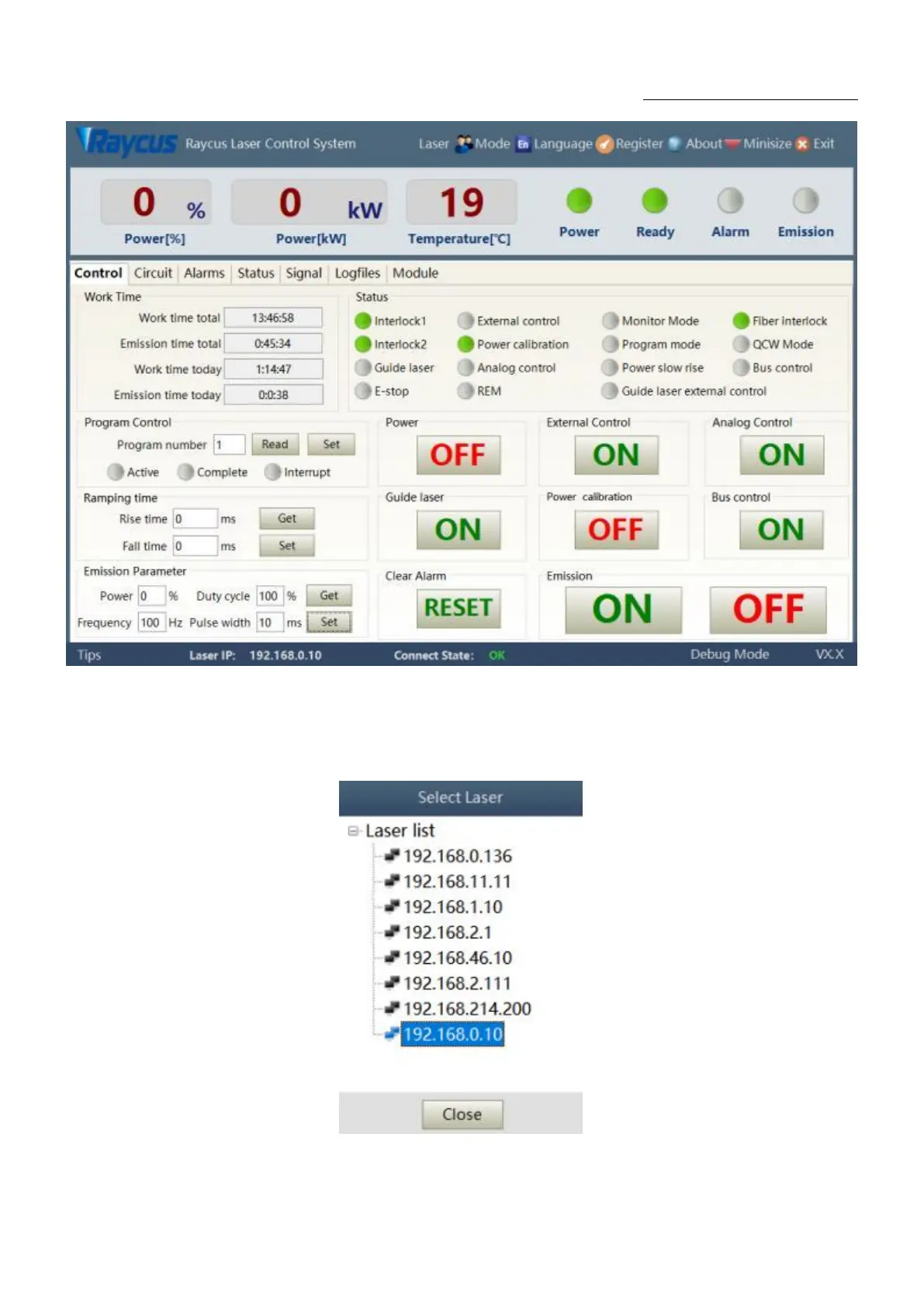
Figure
25PC
software
display
main
interface
8.2.
Multi
-laser
control
area
Multi-laser
control
area
is
as
Figure
26
Figure
26Mul
ti-laser
control
area
interface
49
51
Table of Contents
Main Page
Table of Contents
2
Safety Information
5
Security Label
5
Laser Safety Grade
6
Optical Safety
7
Electrical Safety
7
Other Safety Rules
7
Product Description
8
Features
8
Package Parts
8
Unpacking and Inspection
8
Operation Environment
9
Attentions
9
Specifications
10
Installation
10
Dimensions
10
Installation Rule
13
Protective End Cap of Output Cable and Using Description
15
Types of Protective End Caps and Factory Status
15
Pre-Installation Cleaning Instructions for Output Cables
16
Cooling Requirements
18
Using the Product
21
Front Panel
21
Rear Panel
22
Power Connection
23
Control Interface Definition
24
Safety XP2 Interface
24
Hardwiring Xp1
25
RS232 XP3 Interface
28
Analog Interface XP4
29
INTERNET Interface XP5
29
Introduction to Safety Interlock
29
Schematic Diagram of the Internal Electrical Circuit of the Laser
30
Start Operation Sequence
31
Control Mode Selection
32
ON Mode
34
AD Enable Mode
34
Emisson External Control Enable
34
Guide Laser (Red Guide Beam) Control
35
Programming Mode
35
REM Mode
35
AD Enable Mode
35
Emission External Control
36
Red Light Control
36
Programming Mode
36
Laser Wiring Diagram and Operation Steps
37
Internal Control in on Mode
37
Laser Operating in External Control Mode
38
In on Mode, the Laser Emission Power Is Externally Controlled by Analog Signal
39
Laser Operating in External Control Programming Mode
40
Set the Power Analog Quantity in REM Mode to Control the Laser Emission
41
Power Communication Setting in REM
42
Programming Mode in REM Mode
43
RS232 and INTERNET Communication Command
44
Port Configuration
44
Laser Communication Protocol (Network Port & Serial Port)
45
PC Software Instructions
49
Maininterface of PC Software
49
Multi-Laser Control Area
50
Add/Delete Laser
51
Modifylaserip
52
Main Working Status Display
52
Laser's Cumulative Operating Time Display Area
53
Laserworkingstatusdisplayarea
53
Laser Power-Up, Mode Selection, Light-Out Control Area
55
Programming Mode Test Area
55
Power Slow Rise&Down Parametersettingarea
56
Laser Output Parameters Read the Settings Area
56
Laserparameterdisplayarea
57
Alarm Type Display Area
57
PC Softwareoperatingmodeselection
57
Languagedisplays Laser's All Status and Parameters for Diagnosis Purposes
59
Authorization (Time-Limited Locking)
59
Authorization in User Mode
59
Authorization in Authorization Mode
60
About
61
XP1 Interface Status Indication (in Diagnostic Mode)
62
Log (in Diagnostic Mode)
63
Download Log
64
Downloadrecord of Historicalfault
64
Downloaded File Address
65
Module Parameters (in Diagnostic Mode)
65
Programming Settings (Programming Editing)
65
View the Number of Wave Bars Inside the Current Laser
66
Check Waveform Content
67
Empty All Waveforms
67
Editwaveform
68
Command Explanation
70
Warranty, Repair and Return
72
General Warranty
72
Limitations of Warranty
72
Service and Repair
72
Scrap Requirements
73
Related product manuals
Raycus RFL-C2000
49 pages
Raycus RFL-C2000X
40 pages
Raycus RFL-C2000S-HP
57 pages
Raycus RFL-C200
53 pages
Raycus RFL-C500
53 pages
Raycus RFL-C1000
53 pages
Raycus RFL-C1500
43 pages
Raycus RFL-C3000S
38 pages
Raycus RFL-C4000X
45 pages
Raycus RFL-C1000H
44 pages
Raycus RFL-C4000XZ
80 pages
Raycus RFL-C6000S-CE
55 pages