35
Wuhan Raycus Fiber Laser Technologies Co., Ltd.
User Guide of RFL-C20000M-CE
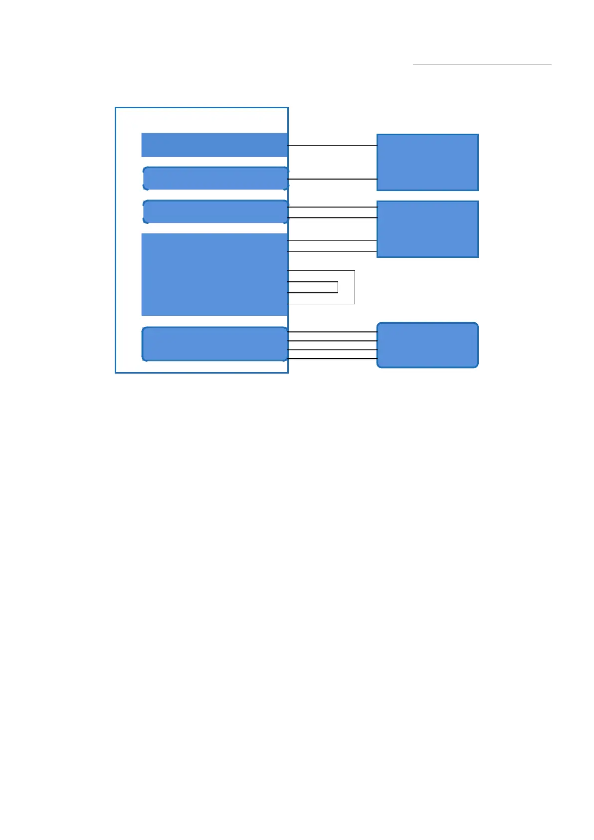
6.3. In ON Mode, the Laser Emission Power is Externally Controlled by Analog Signal
Figure 18In ON mode, the wiring diagram of the power and laser emission controlled by analog signal
Operations Steps
a) Turn the knob switch on the rear panel to“ON”
b)Turn the key switch to“ON”
c) Open the Raycus Laser Control System
d)Click the guide laser “ON” button to view the guide laser
e) Turn on the “AD” mode and turn on “External Control” mode (this mode can be memorized after
power off)
f)Click the main power “ON”
g)Waiting for “Ready”
h)The control board card outputs power analog and emit control signal.