50
Wuhan Raycus Fiber Laser Technologies Co., Ltd.
User Guide of RFL-C20000M-CE
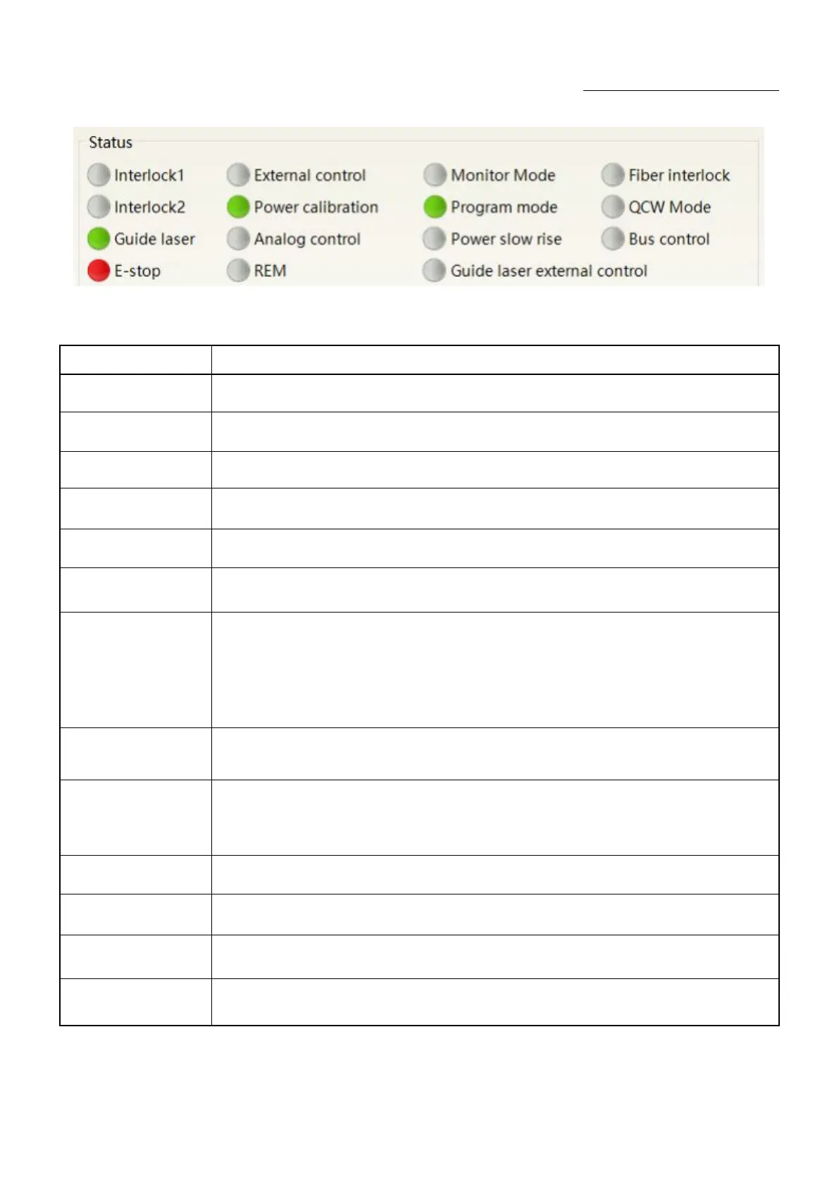
Figure 32A diagram of the laser's working status display area
Table 14The laser main display area clarification
Red: emergency stop button on front panel is pressed
Gray: engergency stop button is reset
Green: laser works in REM mode
Gray: laser works in ON mode
Red laser external
control
Green: laser works in red laser external control mode
Gray: laser works in red laser inernal mode. Laser on/off controllable by software
Green: red laser is on
Gray: red laser is off
Output fiber Interlock
status
Green: Interlock spot at output fiber end is make
Gray: Interlock spot at output fiber end is break
Green: Laser works in external control mode
Gray: laser works in internal control mode. Laser on/off is controllable by software
Green: Laser operates in power linear correction mode, in which control system
automatically adjusts the laser's output power. It makes the output power linear, with a
longer response time for AD analog in this mode, longer than 1mS.
Gray:laser operates in non-correction mode, and the external 0- 10V analog voltage is linear
only with the current of the pump auxiliary tube. The response time for this mode AD
simulation is less than 100uS
Green: Laser power is determined by the 0-10V analog voltage on XP4 when laser works in
AD mode.
Gray: laser power is set by PC software or communication commands.
Green: PC software is in monitoring mode. User can monitor laser status only, but not able
to take control of laser. Monitoring model is activated when interface 10001 of laser
occupied.
Gray: PC software operate in normal mode
Green: XP2 leg 17,18 on safety interface make
Gray: XP2 leg 17,18 on safety interface break
Green: XP2 leg 19,20 on safety interface make
Gray: XP2 leg 19,20 on safety interface break
Green: Laser is in program mode
Gray: Laser is not in program mode
Power slow rise &
fallmode
Green: laser works in power slow rise & fall mode
Gray: laser does not work in power slow rise & fall mode