Chapter 2: Basic Operation 5
2 Basic Operation
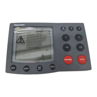
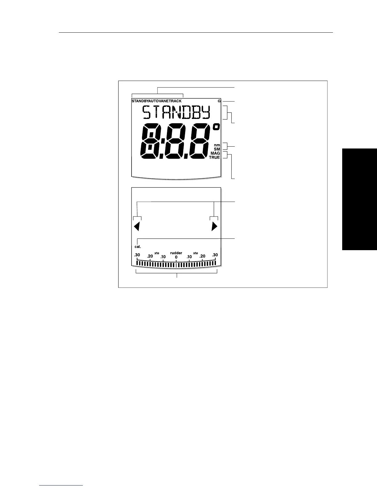
Display layout
The ST7001+ display screen provides the following information:
The bar graph at the bottom of the screen is normally a rudder position
indicator. This indicates the current position of the rudder, as
measured by the rudder position sensor.
Note: You can change this to a heading/cross track/wind error bar in
Display Calibration, see page 79.
Autopilot mode indicators
Rudder position indicator or error bar
GyroPlus indicator (appears if a
yaw sensor is connected to the autopilot)
Variable text area (up to 9 characters)
Port and Starboard
direction-to-steer
indicators
Heading indicators
Calibration mode indicator
(displayed on calibration pages)
D5458-1
Distance units:
• no units = kilometres
• nm = nautical miles
• SM = statute miles