•Thetransducershouldalsobemountedinalocationwherenoloadwillbe
appliedtothetransducerduringlaunching,lifting,traileringandstorageof
thevessel.
6.2T
ransduceranglerequirements
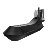
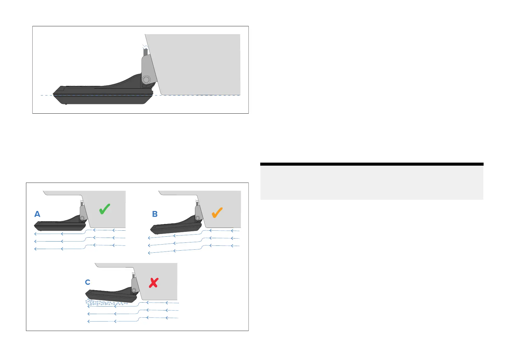
Thefaceofthetransducermustbesettoanappropriateangle.
•A—Forbestresultsthetransducerfaceshouldusuallybeangledsothatit
isparalleltothewaterlinewhilstthevesselisunderway
.
•B—Tiltingthetransducerdownslightlymayberequiredforbestresults
onhighspeedvesselsandvesselsthatrunbow-high.
•C—Tiltingthetransducerupwardsisnotrecommendedasthiscancause
aerationacrossthetransducerface.
6.3EMCinstallationguidelines
Raymarine®equipmentandaccessoriesconformtotheappropriate
ElectromagneticCompatibility(EMC)regulations,tominimizeelectromagnetic
interferencebetweenequipmentandminimizetheeffectsuchinterference
couldhaveontheperformanceofyoursystem.
CorrectinstallationisrequiredtoensurethatEMCperformanceisnot
compromised.
Note:
InareasofextremeEMCinterference,someslightinterferencemaybe
noticedontheproduct.Wherethisoccurstheproductandthesourceof
theinterferenceshouldbeseparatedbyagreaterdistance.
ForoptimumEMCperformancewerecommendthatwhereverpossible:
•Raymarine®equipmentandcablesconnectedtoitare:
–Atleast1m(3.3ft)fromanyequipmenttransmittingorcablescarrying
radiosignalse.g.VHFradios,cablesandantennas.InthecaseofSSB
radios,thedistanceshouldbeincreasedto2m(6.6ft).
–Morethan2m(6.6ft)fromthepathofaradarbeam.Aradarbeam
cannormallybeassumedtospread20degreesaboveandbelowthe
radiatingelement.
•Theproductissuppliedfromaseparatebatteryfromthatusedforengine
start.Thisisimportanttopreventerraticbehavioranddatalosswhichcan
occuriftheenginestartdoesnothaveaseparatebattery.
•Raymarine®specifiedcablesareused.
•Cablesarenotcutorextended,unlessdoingsoisdetailedinthe
installationmanual.
22
 Loading...