Caution:T
ransducercable
•DoNO
Tusethetransducercabletoliftorsuspendthe
transducer;alwayssupportthetransducerbodydirectly
duringinstallation.
•DoNOTcut,shorten,orsplicethetransducercable.
•DoNOTremovetheconnector.
Ifthecableiscut,itcannotberepaired.Cuttingthecablewill
alsovoidthewarranty.
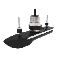
R ealVisiontransducerextensioncables
Y ourtransducerissuppliedwithafittedcable,forsomeinstallations
(includingallsplit-pairtransducerinstallations)itmaybenecessarytoextend
thelengthofthetransducercable.
Note:
•Forbestperformance ,cablerunsshouldbekepttoaminimum.
•OnlyuseRaymarine®transducerextensioncables.
R aymarine®offershefollowingoptionalextensioncablesareavailable:
•RealVision™transducerextensioncable3m(9.8ft)(partnumberA80475)
•RealVision™transducerextensioncable5m(16.4ft)(partnumberA80476)
•RealVision™transducerextensioncable8m(26.2ft)(partnumberA80477)
Splitpairtransducers:Extensioncablesfittedbetweenthetransducerand
the‘Y’cablemustbefittedinequallengthpairs(i.e.:eachtransducer’sfinal
cablelengthmustbethesame).
Warning:Maximumtransducercablelength
ThemaximumlengthofcablebetweenaRealVision™Max
3DtransducerandaMFD/sonarmodule(includingthe
transducer’scaptivecable)mustNOTexceed18m(59ft).
Cablelengthsgreaterthanthismaycausedamagetothe
RealVision™Max3DtransducerandMFD/sonarmodule.
7
.5Mounting
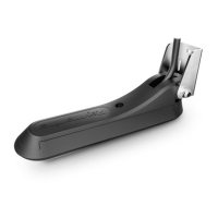
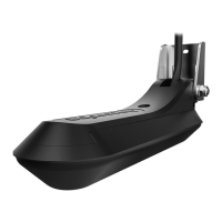
Mountingthetransommountbracket
Thetransducermustbemountedonthetransomusingthemountingbracket
provided.Thestepsbelowdescribetheinitialmountingstepsrequiredin
ordertotestyourtransducer’sperformance.
Important:
•Initiallyonlythe2holesfortheheightadjustmentscrewsarerequired
tosecurethemountingbrack
ettothetransom.Thethirdscrewisused
tofinalizetheinstallationoncethetransducerhasbeentestedand
adjustedtoobtainoptimumperformance.
•Tohelppreventchippingoffiberglasshulls,usepainter’stapetomask
thedrillholeareas,behindthemountingtemplate.
1.Fixthesuppliedtransducermountingtemplatetotheselectedlocation,
usingmaskingorself-adhesivetape.
2.Ensurethetemplateisparalleltothewaterline.
3.Drill2xholesfortheadjustmentslotscrewsasindicatedonthetemplate.
Installation
27
 Loading...