REPRESENTATION
OF
NUMBERS
(Cont'd)
INSTRUCTION
FORMATS
RS
Format
Fixed-Point
Instructions
This
number
representation can be
regarded
as
the
low-order
part
of
an
infinitely long representation
of
the
number. A positive
number
has
all
zero bits, including
the
sign, to the
left
of
the
most significant
bit
of
the
number. A negative
number
has
all one bits, including
the
sign, to
the
left
of
the
most significant
bit
of
the
number. When
an
operand is to be extended
with
high-order bits,
the
extension is made by prefixing
the
operand
with
bits equal to the high-order
bit
of
the
operand.
A negative zero is not included
in
two's-complement notation.
In
the
number
range,
the
set
of
positive numbers is one less
than
the
set
of
negative numbers. The maximum negative
number
is made up
of
an
all-zero
integer
field
with
a one-bit sign. The
maximum
positive
number
consists
of
all
1's
in
the
integer
field with a zero-bit sign. The complement
of
the
maximum negative
number
cannot be represented
in
the
processor.
For
example, on a subtraction
from
zero
that
produces
the
complement
of
the
maximum negative number, a fixed-point overflow exception is noted
and
the
number
remains unchanged.
If
the final result is
within
the
represent-
able range, then
an
overflow does
not
result
(such
as
a
subtraction
from
minus one). The representation of
the
product
of
two maximum negative
numbers is a double-length positive number.
An overflow
carries
into
the
leftmost bit, which is
the
sign,
and
changes
it.
In
algebraic shifting, however,
the
sign
bit
is unchanged even when
significant bits
in
a
shift
left
instruction
are
shifted out.
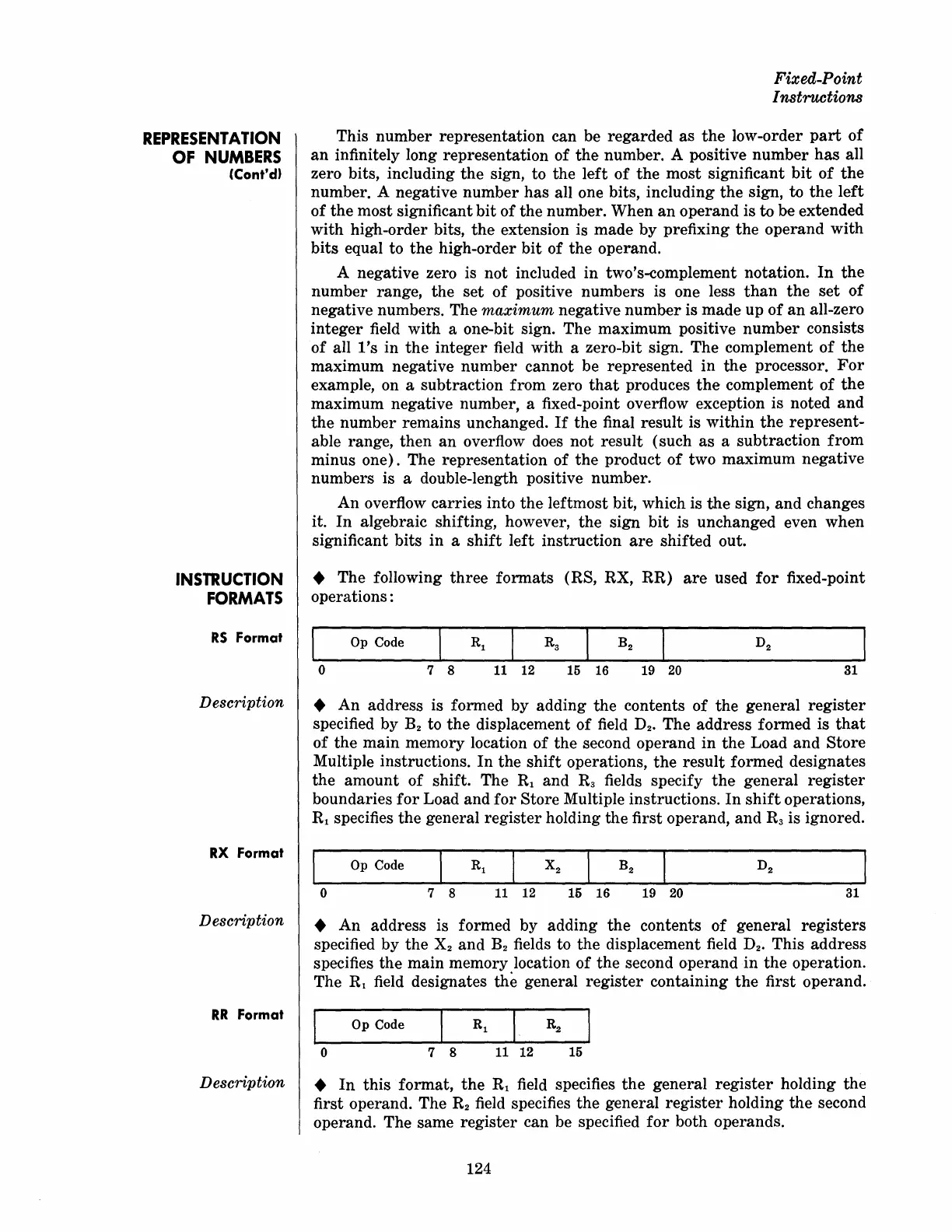
• The following
three
formats
(RS, RX,
RR)
are
used
for
fixed-point
operations:
o
7 8 11 12 15 16 19 20
31
Description •
An
address is formed by adding the contents
of
the general
register
specified by
B2
to
the
displacement
of
field D
2
. The address formed is
that
of
the
main
memory location
of
the
second operand
in
the
Load
and
Store
Multiple instructions.
In
the
shift
operations,
the
result
formed designates
the
amount
of
shift. The Rl and
R3
fields specify
the
general
register
boundaries
for
Load and
for
Store Multiple instructions.
In
shift
operations,
Rl specifies the general
register
holding the first operand,
and
R3
is ignored.
RX Format
Description
RR
Format
Description
Op Code
o 7 8
11 12
15 16 19
20
31
•
An
address is formed by adding
the
contents
of
general
registers
specified
by
the X
2
and
B2
fields to
the
displacement field D
2
. This address
specifies
the
main memory location
of
the
second operand in
the
operation.
The Rl field designates
the
general
register
containing
the
first operand.
Op Code
o
7 8
11 12
15
•
In
this
format,
the
Rl field specifies
the
general
register
holding the
first operand. The
R2
field specifies
the
general
register
holding
the
second
operand. The same
register
can be specified
for
both operands.
124