CAUTION
If for any reason you do not understand the test procedures or are unable to perform the tests/repairs safely, contact your
Local Authorized Field Service Facility
for technical troubleshooting assistance before you proceed.
INSTALLATION DIAGRAM
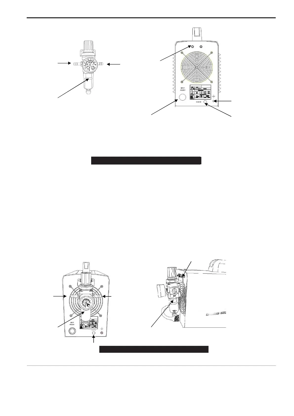
1-1 1-2 2-1
1 Air Regulator 2-4
2-2 Back of machine 2-3
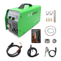
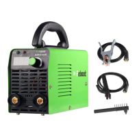
1. Air regulator
This is air regulator, This part is supplied along with machine, You will see it after you open carton. 1-1.
This terminal fix on a side of hose for air in, another side of hose connecting air compressor
1-2. This terminal fix one side of hose for air out. Another side of hose for fix on picture 2-3.
W
ARNIN
G
Clean, dry air must be supplied to the machine. A pressure setting above 110 PSI (7.5 bar) could
damage the torch. Failure to observe these precautions could result in excessive operating temperatures
or damage to the torch.
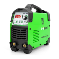
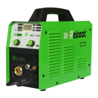
2. Back of machine.
This is back of machine, Air regulator will be fixedthere.
2-1. This is screw for fix air regulator. Please be sure screw fasten after fix it. 2-2.
This is power cable, Connecting 220V or 110V.
2-3. This is air in, A terminal of hose connecting here, Another terminal connecting air regulator 1-2 2-4.
Do not use this connection, Please just ignore it.
3-2
4
3-3
 Loading...