EasyManua.ls Logo

Reboot RBM2000P - User Manual

Reboot RBM2000P
23 pages
Print Icon
To Next Page IconTo Next Page
Loading...
Version Number: RBM2000P-20210517A1
1
Operation Manual
Reboot RBM2000P welding machines adopts the latest pulse width modulation (PWM) technology and
insulated gate bipolar transistor (IGBT) power module, which can change work frequency to medium frequency so as
to replace the traditional Transistor transformer with the medium frequency transformer. its characterized with
portable, small size, light weight, low consumption and etc. It is also an intelligent and easy-to-operate multi-function
welding machine with MMA, MIG GAS, MIG GASLESS and pulse MIG. It has the characteristics of strong welding
performance and diversified usage scenarios. It can be used in both gas and gasless conditions, especially for
welding aluminum, the shape is particularly good ,and the welding effect is excellent. It is highly praised by welding
enthusiasts. It is also very friendly to beginners in welding and can quickly get started.
Part 1: Machine Introduction
1. Current display meter
The digital Ammeter is used to display preset current.
When the MENU” light is on, it is also used to display menu items.
Depending on the menu item selected, the status indictor adjacent to the Ammeter will illuminate to show
the units of the programming parameter.
When welding, the Ammeter will display actual welding current.
2. Voltage display meter
The digital Ammeter is used to display preset voltage.
When the “MENU” light is on, the parameters of each menu item are displayed
When the “INDUCT” light is on, the inductance adjustment value is displayed.
When welding, the Ammeter will display actual welding voltage.
3. Current indicator.
4. MENU indicator.
Question and Answer IconNeed help?

Do you have a question about the Reboot RBM2000P and is the answer not in the manual?

Summary

Part 1: Machine Introduction

Current and Voltage Display Meters

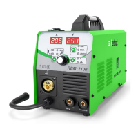
Details about the current and voltage display meters and related indicators.

Control Knobs and Welding Mode Selection

Explanation of control knobs (A, B) and how to select the welding mode.

Part 2: Product Introduction and Configuration

Connectors and Terminals

Description of MIG welding torch connector, positive and negative terminals.

Welding Machine Unit and Initial Checks

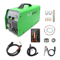
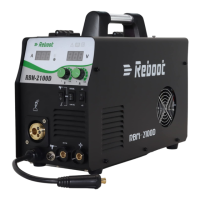
Overview of the RBM2000P welding machine unit and initial inspection requirements.

Welding Torches and Holder

Details on MB24 and MB15 MIG welding torches, and welding holder.

Accessories and Consumables List

Accessories and Consumables List

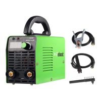
List and description of accessories like ground clamp, hose, clamps, tips, wire feed wheels, wire, and manual.

Part 3: Simple Test for Powering On

Power-On Inspection Precautions

Essential precautions before powering on the welding machine for the first time.

Power-On Test Notes and Troubleshooting

Normal behavior during startup and troubleshooting for initial power-on issues.

Part 4: Technical Specifications

Basic Machine Parameters

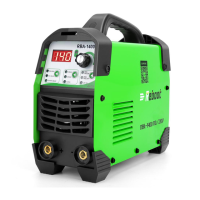
Key technical specifications of the RBM2000P welding machine.

Manual Welding Parameters (MMA Mode)

MMA Mode Settings

Rated current, hot start, and factory reset settings for MMA welding.

Unified Gas Shielded Welding Parameters (SYNC MIG)

SYNC MIG Mode Settings

Parameters for SYNC MIG welding, including current, arc length, material, wire diameter, modes, and timings.

Part 5: Operation Panel Instructions

First Level Panel Setting Interface

Description of the primary interface for current, voltage, and welding mode selection.

Second Level Panel Setting Interface

Explanation of the secondary interface for advanced parameter adjustments.

Parameter Codes and Abbreviations

Parameter Codes and Abbreviations

Table of parameter codes, abbreviations, and their introductions for advanced settings.

Part 6: Machine Operation Guidance

General Welding Safety Tips

Essential safety tips for welding, including protective gear and precautions.

MMA Mode Operation Guide

Selecting MMA Process

Step-by-step guide to select the MMA welding process on the machine.

Connecting Holder and Ground Clamp

Instructions for connecting the welding holder and ground clamp for MMA welding.

Adjusting MMA Parameters

Adjusting MMA Parameters

How to adjust current, arc force, and hot start parameters for MMA welding.

MMA Mode Notes and Material Support

Notes on welding rods, supported materials (steel), and ground clamp connection.

MIG Mode Operation Guide

MMA Mode Troubleshooting

Troubleshooting common issues encountered during MMA welding.

Common Gas Shielded Arc Welding

Guide to common gas shielded arc welding and gasless self-shielded welding.

Setting Polarity for MIG Solid Wire

Setting Polarity for MIG Solid Wire

How to set polarity for solid wire welding with and without gas protection.

Connecting MIG Gun and Ground Clamp

Instructions for connecting the MIG gun and ground clamp for MIG welding.

Installing Wire Spool

Guide on how to install different sizes of wire spools onto the machine.

Wire Feed and Pressure Adjustments

Setting Drive Roll for Wire Diameter

How to set the drive roll to match the welding wire diameter (0.8mm/1.0mm).

Feeding Wire and Setting Pressure

Instructions for feeding wire and adjusting the pressure for stable wire feeding.

Connecting Power and Gas

Connecting the machine to input power and setting up CO2 gas or flux-cored wire.

Welding Torch Installation

Steps for installing the welding torch and ensuring proper wire feeding.

Wire Feed and Control Adjustments

Wire Feed and Control Adjustments

Procedure to remove consumables and adjust wire feed speed, current, and voltage.

Adjustable Parameters for Gas;Gasless Shielded Arc Welding

Current, Arc Length, and Inductance

How to adjust current, arc length, and inductance for gas/gasless shielded arc welding.

Operating Modes (2 T;4 T) Selection

Explanation of how to select operating modes, specifically 2T and 4T.

Arc Initiation and Wire Replacement

Steps for initiating the arc and procedures for replacing the welding wire.

Welding Gun Installation Details

Wire Feeding Pipe and Torch Match

Ensuring correct wire feeding pipe and torch match for smooth welding and preventing overheating.

Structure of Welding Gun (TORCH 15)

Torch Components and Wearing Parts

Identification of torch components, including wearing parts like nozzle and conductive nozzle.

Wire Compatibility and Feed Issues

Notes on supported wire types, wire feed wheel matching, and pressure roller adjustments.

Troubleshooting Torch Connection and Feed

Troubleshooting common issues related to power, wire feeding, and gun winding.

Pulse Gas Shielded Arc Welding

Selecting Pulse MIG Process

How to select Pulse/Al/Mg or Pulse/Al/Si process based on aluminum wire material.

Setting Polarity for MIG Aluminum Wire

Procedure for setting polarity for solid wire MIG aluminum welding with gas protection.

Aluminum MIG Welding Setup

Connecting MIG Gun and Ground Clamp

Instructions for connecting the MIG gun and ground clamp for solid aluminum wire welding.

Installing Wire Spool and Setting Drive Roll

Guide to installing wire spools and setting drive rolls for different aluminum wire diameters.

Gas Welding with U-type Wire Feed Wheels

Using U-type wire feed wheels for aluminum welding wire with Argon gas.

Aluminum MIG Wire Feeding and Gas Setup

Feeding Wire and Setting Pressure

Adjusting wire feed pressure for stable feeding of aluminum wire.

Connecting Power and Argon Gas

Connecting the machine to input power and setting up Argon gas for welding.

Welding Torch Installation for Aluminum

Installing the welding torch with Teflon hoses for feeding aluminum wire.

Adjustable Parameters for Gas Shielded Arc Welding

Wire Feed and Control Adjustments for Gas Welding

Procedure to remove consumables and adjust wire feed speed, current, and voltage for gas shielded welding.

Current, Arc Length, and Inductance

How to adjust current, arc length, and inductance for gas shielded arc welding.

Operating Modes (2 T;4 T)

Explanation of selecting operating modes, 2T and 4T, for gas shielded welding.

Initiating Arc

Steps for initiating the arc with the contact tip at 1/4 inch from the metal.

Replacing the Welding Wire

Wire Replacement Procedure

Steps to cut excess wire, loosen pinch wheel, and return wire to the reel.

Structure of Welding Gun (TORCH 24)

Torch Components and Aluminum Liners

Identification of TORCH 24 components, including guide wire tube for aluminum.

Welding Wire and Material Compatibility

Welding Wire and Material Compatibility

Notes on supported aluminum wire diameters, wire reels, and material compatibility.

Wire Feeding and Connection Troubleshooting

Troubleshooting wire feeding instability, loose connections, and power issues.

Part 7: Alarm Codes

Memory Chip and Output Insulation Faults

Troubleshooting for memory chip exception and output insulation failure alarms.

Motor Current, Speed Feedback, and Overheating

Troubleshooting motor current, speed feedback line, and inverter overheating alarms.

Phase Loss, No-Load, Short Circuit, and VRD Faults

Troubleshooting phase loss, no-load, short circuit, and VRD faults.

Operation Errors and Sticky Welding Rods

Troubleshooting human errors and issues with sticky welding rods.

Reboot RBM2000P Specifications

General IconGeneral
BrandReboot
ModelRBM2000P
CategoryWelding System
LanguageEnglish

Related product manuals