Version Number: RBM2000P-20210517A1
Part 5: Instructions of Operation Panel
The welding machine has two operating interfaces: first level panel setting interface and second level
parameter setting interface.
First level panel setting interface
After starting up, the welding machine will automatically enter the first level panel setting interface.
During welding, it will also automatically enter the first level panel setting interface.
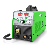
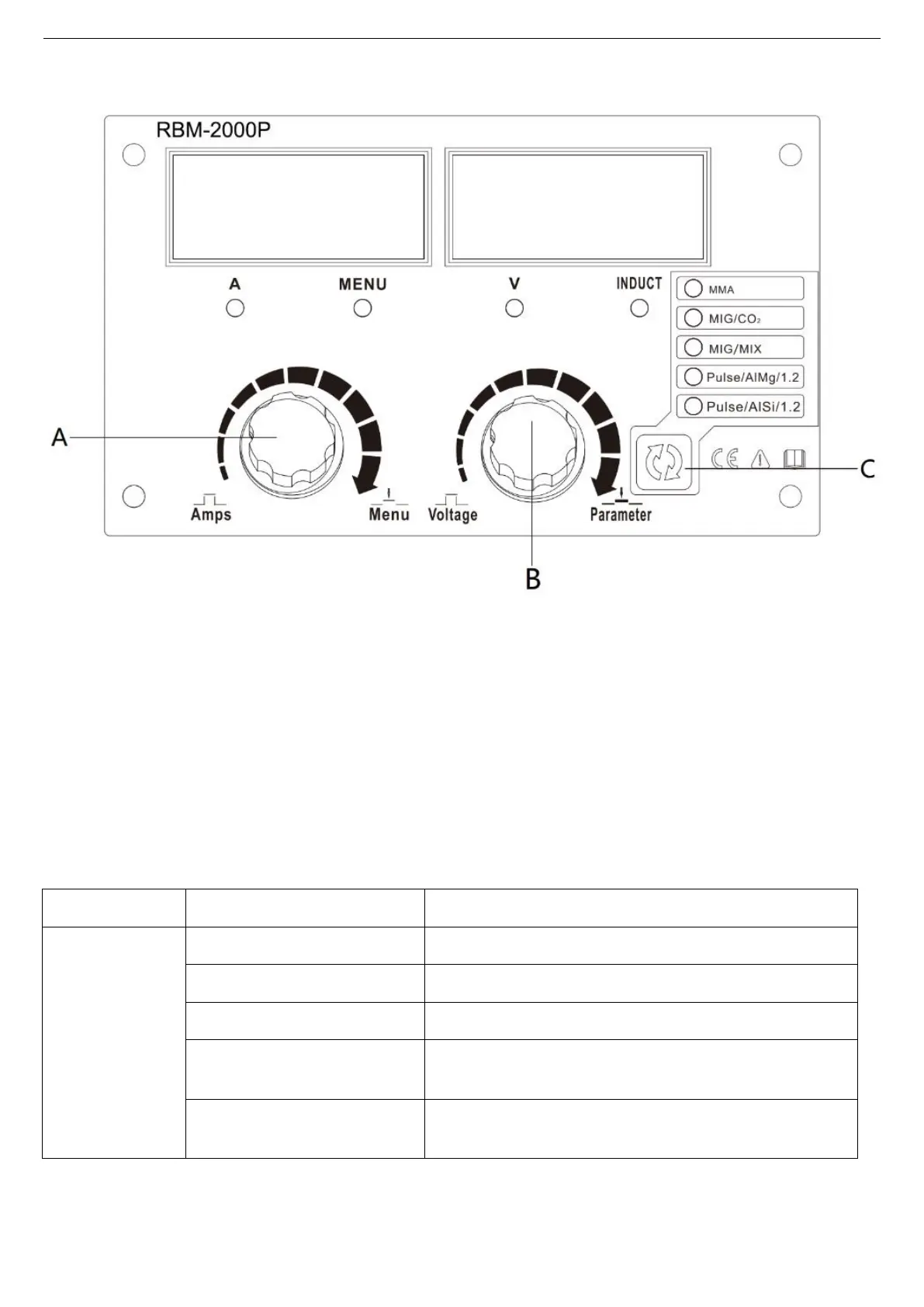
(1) Current and voltage regulation
Knob A is used for regulating the current, and knob B is used for regulating the voltage/arc length.
(2) Selection of welding mode
Button C is used for selecting the welding mode. See Table 5-1 Comparison Table of Welding Modes
for specific welding modes.
Table 5-1
Manual covered-electrode welding.
Common gas shielded arc welding, carbon dioxide.
Common gas shielded arc welding, mixed gas.
Aluminum-magnesium pulse gas shielded arc welding, wire
diameter of 1.2.
Aluminium-silicon pulse gas shielded arc welding, wire
diameter of 1.2.
Remark: the unified default wire diameter of RBM2000P common gas shielded arc welding is 0.8mm. If
1.0mm wire is required, the parameters shall be matched manually .
(3) Regulation of arc force parameter
Press knob B, then the arc force indicator light (INDUCT) is on, and rotate knob B to adjust the arc length.
 Loading...