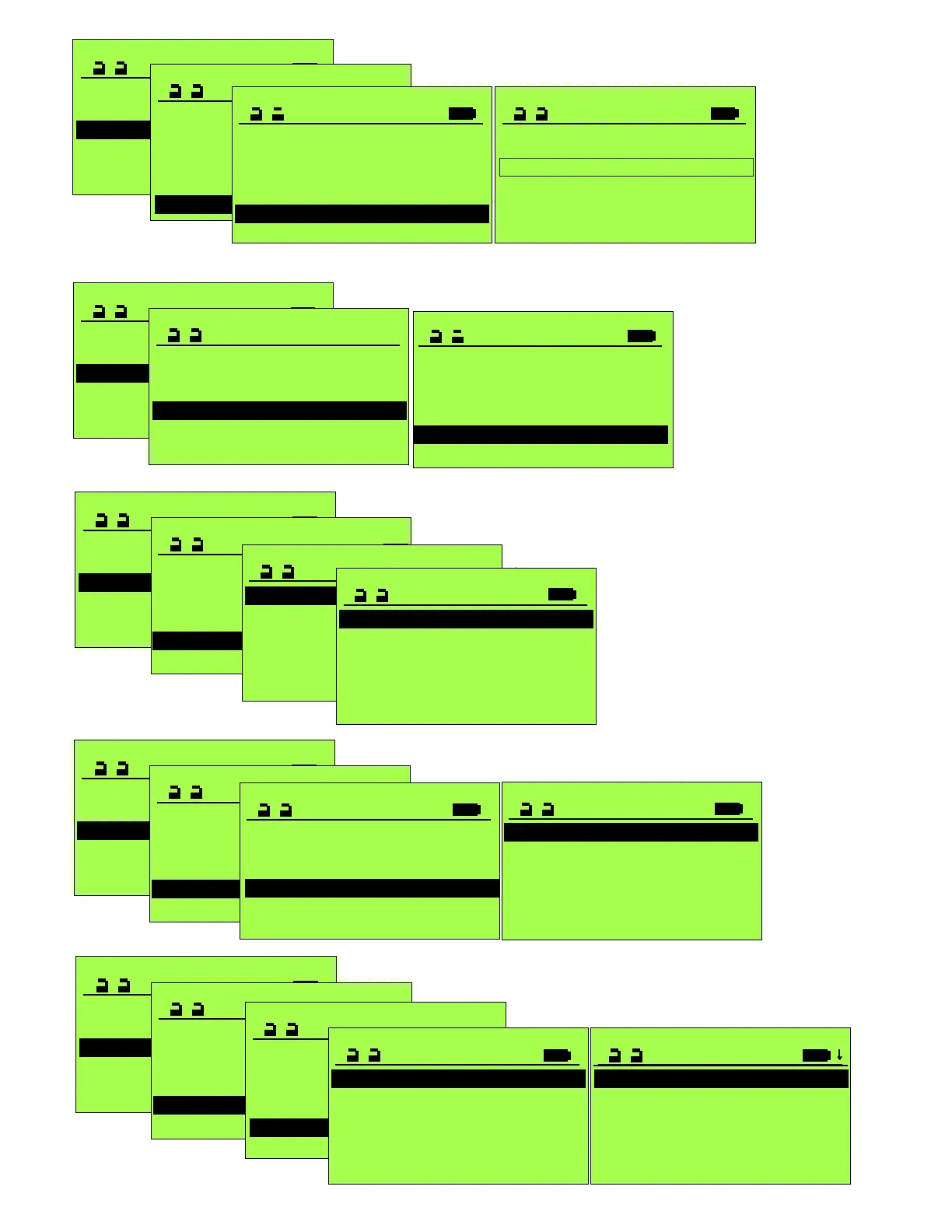
Operation mode >
SERVICE STG
Maintenance >
Functions >
Configure System
Learning System >
Parameter >
PARAMETER
Driving Cycle >
Time delay open >
Drive >
Entrance System >
Control Panel >
Locking >
LOCKING
Locking functions 2
Lock type
Start Delay 0
Closed VRR Error 0
Closing Force 0
Closed VRR Error
0 Disabled
1 Enabled
Closed VRR Error
0 Disabled
1 Enabled
Closed VRR Error
0 Disabled
1 Enabled
Closing Force
0
Briefly increases
closing force to
relieve locking bolt.
0=low force
40=high force
During Start Delay,
door is powered in
closing direction to
relieve any binding
on electric lock.
Operation mode >
SERVICE STG
Maintenance >
Functions >
Configure System
Learning System >
Parameter >
PARAMETER
CAN-BUS >
Input/Output >
Miscellaneous >
Entrance System >
Control Panel >
Locking >
CAN-BUS
FEM0 0
FEM1 0
FEM2 0
AKI1 0
S I1 0
AKI1 0
Any Can-Bus module or
sensor connected is
automatically identified &
displayed with a "1".
Disconnected units are
displayed with "?" and must
be removed manually with
FPC902. Not available units
are displayed with a "0".
Operation mode >
SERVICE STG
Maintenance >
Functions >
Configure System
Learning System >
Parameter >
PARAMETER
CAN-BUS >
Input/Output >
Miscellaneous >
Entrance System >
Control Panel >
Locking >
INPUT/OUTPUT
Ext. Sw IN 0
Emerg. Open/Close 0
EMERG, STOP Reset 0
STG >
FEM0 >
FEM1 >
Operation mode >
SERVICE STG
Maintenance >
Functions >
Configure System
Learning System >
Parameter >
PARAMETER
CAN-BUS >
Input/Output >
Miscellaneous >
Entrance System >
Control Panel >
Locking >
STG
AUX0_OUT 0
ZLP >
AUX0_IN 0
AUX1_IN 0
AUX4_IN 0
Configurable Input Terminals 4,6,and
18 on STG Control. Note: With
parameters identified as “Safety”, a
closed contact is required for normal
door operation.
AUX0_OUT: Dry contacts on STG to
Terminals 8(NO), 9(COM), 10(NC)
Rated @ 1 Amp 30VDC.
ZLP1: Additional Circuit Board to
connect threshold Safety Beams.
Set ELS to be active. See S5100
Parameter Settings record sheet.
Operation mode >
SERVICE STG
Maintenance >
Functions >
Configure System
Learning System >
Parameter >
PARAMETER
CAN-BUS >
Input/Output >
Miscellaneous >
Entrance System >
Control Panel >
Locking >
Operation mode >
SERVICE STG
Maintenance >
Functions >
Configure System
Learning System >
Parameter >
PARAMETER
CAN-BUS >
Input/Output >
Miscellaneous >
Entrance System >
Control Panel >
Locking >
FEM0,FEM1
contain settings
for input/outputs
for Expansion
Modules.
Ext. Sw IN;
INPUT/OUTPUT
Ext. Sw IN 0
Emerg. Open/Close 0
EMERG, STOP Reset 0
STG >
FEM0 >
FEM1 >
EMERG. OPEN/CLOSE
Function 0
Speed (Flip Flow only) 0
FUNCTION
0 Disabled
1 Emergency Open
2 Emerg. Close
Manual&RemSw
3 Emerg. Close
Locked
Five
options
listed.
Responds to AUX00_IN, AUX01_IN or AUX04_IN set to “2SoK_NSK and the control wired appropriately.
Ext. Sw IN
0 Ext. Sw IN
1 Inactive by 1 Way
5 Disabled
INPUT/OUTPUT
Ext. Sw IN 0
Emerg. Open/Close 0
EMERG, STOP Reset 0
STG >
FEM0 >
FEM1 >
and locked
Enable to comply with ANSI/BHMA A156.10for Exterior
sensor to be active in Exit mode and the door is open.
 Loading...


