EasyManua.ls Logo

RED DEVIL 1400 User Manual

RED DEVIL 1400
32 pages
To Next Page IconTo Next Page
Page #1 background imageLoading...
Page #1 background image
Owner’s Manual:
1400 & 1410 Air & Explosion
One-Gallon Shaker
Models 1400, 1410-A1, 1400-X1
www.radiaproducts.com (PHONE) 800-221-1083 | (INTL) +1-763-533-2969 | (FAX) 763-533-0015
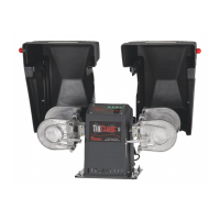
1410-A1 on Counter Base
(5153-00)
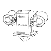
1400-X1 on Pedestal Base
(5151-00)

Questions and Answers:

RED DEVIL 1400 Specifications

General IconGeneral
BrandRED DEVIL
Model1400
CategoryPaint Sprayer
LanguageEnglish

Summary

Safety Information

Safety Notification Labels

Explains the meaning of WARNING, CAUTION, and NOTICE labels used on the machine.

Safety Precaution Labels

Electrical and Grounding Warnings

Details electrical safety warnings and grounding requirements.

Air Supply Pressure Limits

Specifies safe air supply pressure limits for the equipment.

Moving Parts and Guard Safety

Outlines safety measures for moving parts and guard operation.

Safety Precaution Summary

General Operation and Maintenance Safety

Provides a summary of operational safety practices and maintenance precautions.

Introduction

Application

Describes the intended uses and capabilities of the shaker machine.

Specifications

Details unit dimensions, shipping weight, electrical and air service requirements.

Assembly and Test

Prepare for Use

Steps to prepare the machine before assembly and operation.

Assemble Countertop Base

Instructions for assembling the shaker onto a countertop base.

Assemble Pedestal Base

Instructions for assembling the shaker onto a pedestal base.

Connect to Power

Electrical Connection (X1 Models)

Guidance for connecting the 1400-X1 model to electrical power.

Air Connection (A1 Models)

Guidance for connecting the 1410-A1 models to air power supply.

Test Operation

Anchoring the Pedestal Unit

Procedures for anchoring the pedestal unit to the floor if it moves during operation.

Operation

Install a Pail and Mix

Step-by-step guide on how to load and secure a container for mixing.

Care & Maintenance

Cleaning Procedures

Procedures for cleaning the shaker machine to ensure optimal performance.

General Maintenance (All Models)

Routine maintenance procedures applicable to all shaker models.

Model-Specific Maintenance (1400-X1)

Specific maintenance tasks for the 1400-X1 model, including belt tension.

Maintenance (Air Models)

Air Filter Maintenance

Steps for draining the air filter and replacing the filter element.

Air Lubricator Maintenance

Procedures for refilling and adjusting the air lubricator for proper motor lubrication.

Troubleshooting

Mixer Operation Issues

Troubleshooting guide for mixer not operating, slow start, or slow running.

Pail and Clamp Problems

Addresses issues with pail fitting, secure clamping, and clamp issues.

Shut-off and Movement Issues

Solutions for mixer not shutting off correctly or walking during operation.

Noise Issues

Identifies causes of excessive noise and provides remedies for the shaker.

Wiring Diagrams

1400-X1 Model Wiring Diagram

Electrical wiring schematic for the 1400-X1 explosion-proof model.

1400 & 1410-A1 Pneumatic Schematic

Pneumatic System Overview

Diagram of the air system components for 1400 & 1410-A1 models.

Exploded Views

Drive System 1400-X1

Exploded view of the drive system components for the 1400-X1 model.

Transmission Assembly

Transmission Components

Exploded view of the transmission assembly and its parts.

Drive System 1400 & 1410-A1

Drive System Components (1400/1410-A1)

Exploded view of the drive system components for 1400 & 1410-A1 models.

Air Assembly

Air System Components

Exploded view of the air system components used in the shaker.

Clamp Assembly, Left

Left Clamp Assembly Parts

Exploded view of the left side clamp assembly and its constituent parts.

Clamp Assembly Right

Right Clamp Assembly Parts

Exploded view of the right side clamp assembly and its constituent parts.

Enclosure Assembly (1400-X1)

Enclosure Components (1400-X1)

Exploded view detailing the enclosure components for the 1400-X1 model.

Clamp Cover Assembly (1400-X1 & A1)

Clamp Cover Assembly Parts

Exploded view of the clamp cover assembly for both 1400-X1 and 1410-A1 models.

Electrical Assembly (1400-X1)

Electrical System Components (1400-X1)

Exploded view of the electrical components for the 1400-X1 model.

Counter Base (5153-00)

Counter Base Parts

Exploded view of the counter base assembly and its parts.

Pedestal Base (5151-00)

Pedestal Base Parts

Exploded view of the pedestal base assembly and its parts.

Ordering

How to Order Replacement Parts

Instructions and contact information for ordering replacement parts from Radia.

Warranty

Warranty Coverage Details

Details the equipment models covered and the terms of the manufacturer's warranty.

Notes

Related product manuals