Installation Wiring Diagrams
19
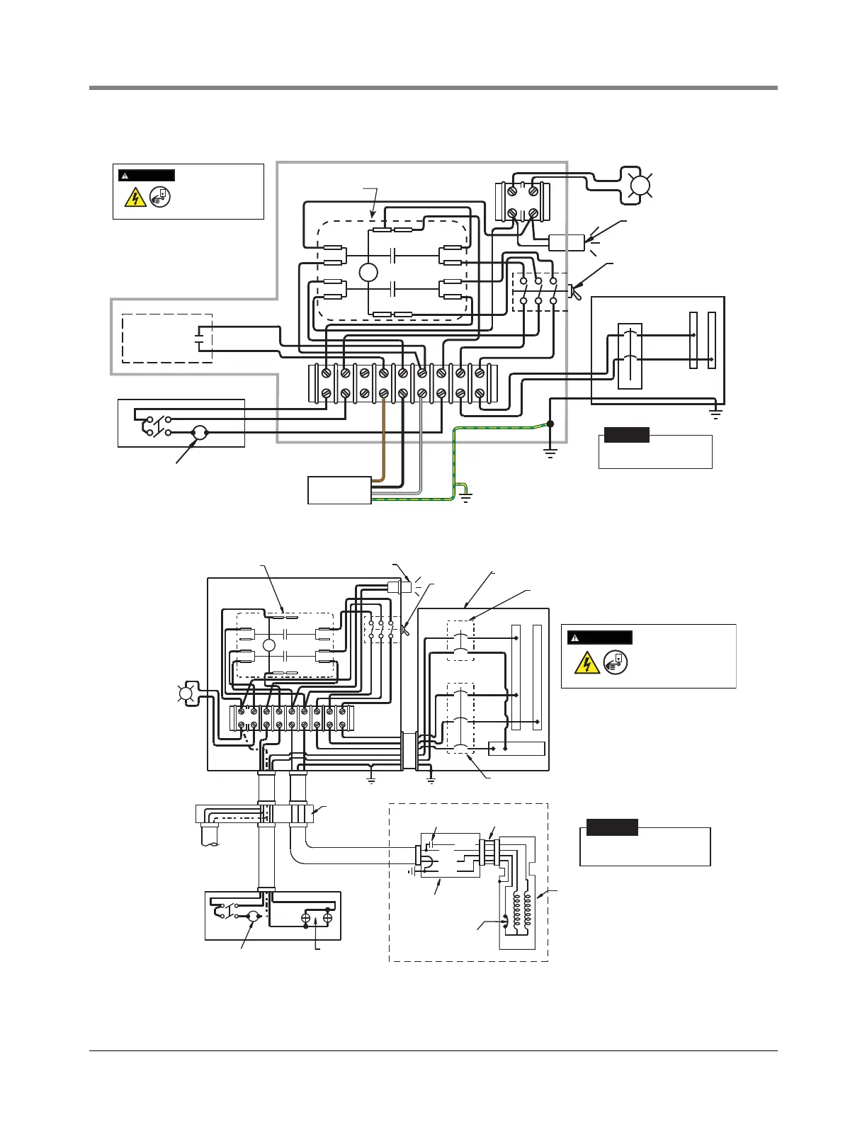
Figure 18. 240 Vac Remote Control Box With 240 Vac Coil And Capacitor (Models 410860-001 Or 410860-003)
Figure 19. 230 Vac Remote Control Box With 110Vac Coil - Model 880-041-5
LOAD CENTER
220 OR 240 VOLT
L2L1M1M2M3 S3S2S1
P
3 P.S.T.
TOGGLE
SWITCH
PILOT LIGHT
LINE STARTER
EXT
PILOT
LIGHT
240 VOLT
25 WATT MAX.
CAPACITOR
PH N
BLACK
BROWN
UMP
GREEN/YELLOW
GREY
Dispenser
Optional solenoid valve
(76 volt-amps max.)
DISCONNECT, LOCK OUT,
AND TAG POWER AT THE
POWER PANEL BEFORE
WIRING THE PUMP.
WARNING
OFF
Make ground connection in
accordance with local codes.
NOTICE
Connect To
Electrical Ground
Dispenser
lights
External
pilot light
(115 volts)
25 watt max.
Optional other
dispenser
(max. total of
6 dispensers)
EXT
PILOT
LIGHT
15A-3P switched
neutral breaker
1 phase, 3 wire 15A-2P switched
neutral breaker
Load center 208 or 230 volt
3 P.S.T.
toggle
switch
Pilot light
Line starter
Dispenser
Wiring
trough
Optional solenoid valve
(76 volt amps. max)
N
L2 L1
S1
S2 M2 M1 N L1 L2
DISCONNECT, LOCK OUT,
AND TAG POWER AT THE
POWER PANEL BEFORE
WIRING THE PUMP.
WARNING
OFF
Make ground connection in
accordance with local codes.
NOTICE
Cable Strain
Relief
Internal
overload
protector
Continuous
duty capacitor
Submersible
DEF pump
Motor
Brown
Black
Green
Grey
Liquid-Tight
Junction Box