4” Standard Pump Installation, Operation & Service Manual Specifications
9
Table 3 shows pump electrical service requirements for UMPs with end view A and Table 4 shows pump elec-
trical service requirements for UMPs with end view B.
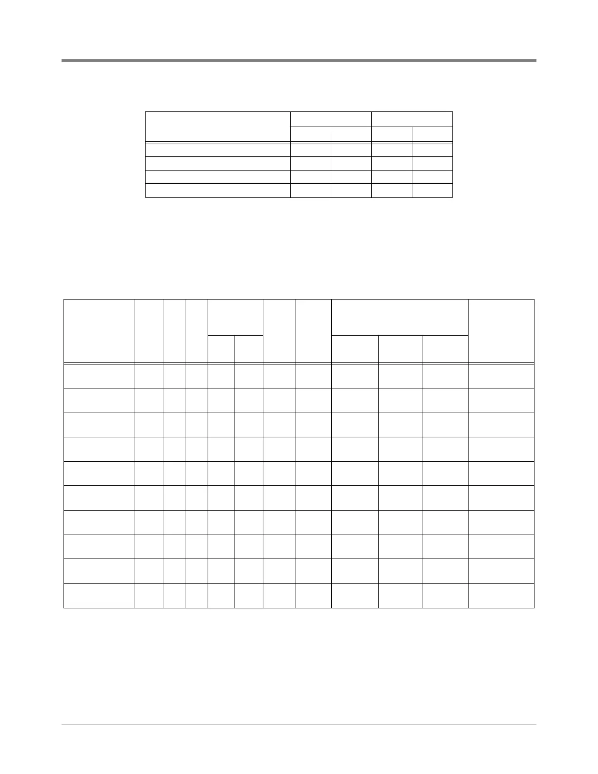
X4P150S17T1, X4AGP150S17T1 74.5 1892 101.5 2578
X4P150S17T2, X4AGP150S17T2 97.5 2476 131.5 3340
X4P150S17T3, X4AGP150S17T3 131.5 3340 198.5 5041
X4P150S17T4, X4AGP150S17T4 131.5 3340 165.5 4203
Table 3.- Electrical Service Information (Use for UMPs Containing a Franklin Motor with End View A)
Required power supply rating for 60 Hz, 1 phase motors is 208 - 230 Vac. For 50 Hz, 1 phase motors, required rating is 220 - 240 Vac.
3 phase motors required rating is 380 - 415 Vac.
UMP Model No. HP Hz PH
Voltage
Fluctuation
Range
Max.
Load
Amps
Locked
Rotor
Amps
Winding Resistance (Ohms)
Capacitor Kit
(µF) or Heaters
(KXX)Min. Max.
Black-
Orange
Red-
Orange Black-Red
AGUMP33R1,
UMP33R1
1/3 60 1 200 250 4 13 7.7 - 9.4 17.4 - 21.2 25 - 30.7 144-224-5 (17.5)
AGUMP75S1,
UMP75S1
3/4 60 1 200 250 6.5 25 2.9 - 3.6 14.9 - 18.2 17.7 - 21.9 144-224-5 (17.5)
AGUMP150S1,
UMP150S1
1-1/2 60 1 200 250 10.5 37 2 - 2.5 11.6 - 14.2 13.5 - 16.8 144-225-5 (25)
X3AGUMP150S1,
X3UMP150S1
1/1/2 60 1 200 250 10.5 37 2 - 2.5 11.6 - 14.2 13.5 - 16.8 144-225-5 (25)
AGUMP75S3-3,
UMP75S3-3
3/4 50 1 200 250 5.8 17 3.6 - 4.5 20.4 - 25 23.9 - 29.6 144-224-5 (17.5)
AGUMP150S3-3,
UMP150S3-3
1-1/2 50 1 200 250 10 28 2.5 - 3.1 11.5 - 14 13.9 - 17.2 144-225-5 (25)
X4AGUMP150S3,
X4UMP150S3
1-1/2 50 1 200 250 10 28 2.5 - 3.1 11.5 - 14 13.9 - 17.2 144-225-5 (25)
AGUMP75S17-3,
UMP75S17-3
3/4 50 3 342 457 2.2 11 25.8 - 32.4 25.8 - 32.4 25.8 - 32.4 K26
AGUMP150S17-3,
UMP150S17-3
1-1/2 50 3 342 457 3.8 15.8 13.1 - 16.4 13.1 - 16.4 13.1 - 16.4 K33
X4AGUMP150S17,
X4UMP150S17
1-1/2 50 3 342 457 3.8 15.8 13.1 - 16.4 13.1 - 16.4 13.1 - 16.4 K33
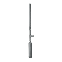
Table 2.- Distance From Eye Bolt to Inlet
MODEL#
COMPRESSED EXTENDED
in mm in mm