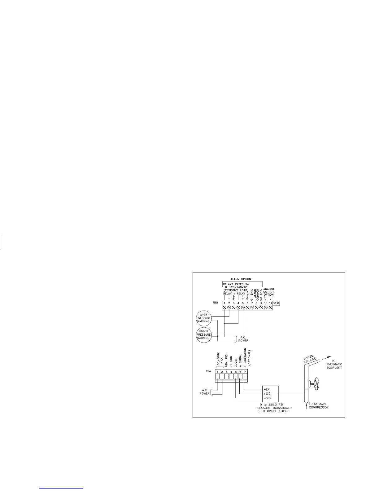
PNEUMATIC PRESSURE EXAMPLE
An IMD1 is employed to monitor and display the pneumatic (air) pressure
of a robotic assembly system at a manufacturing plant. Several “dedicated”
robotic arms are used to fasten bolts which join pieces of material together.
The robotic arms will operate correctly, so long as the system pressure
remains between 160.0 to 180.0 PSI. If the pressure were to drop below 160.0
PSI, the bolts would not be properly fastened. If the pressure became greater
than 180.0 PSI, then the bolts would be over tightened and the threads may
strip, or damage to the product may occur.
A 0-10 VDC (0-250.0 PSI) linearized pressure transducer is used and the
±20 V range of the IMD is selected. The IMD is scaled to display0@0VDC
and 250.0 @ 10 VDC. Alarm #1 is programmed to activate a warning signal
when the pressure exceeds 180.0 PSI. Alarm #2 is programmed to latch and
activate a warning bell and light if the pressure falls below 160.0 PSI. The
software option is specified, to record daily high (peak) and low (valley)
pressures to assist in isolating any pressure problems within the system.
Basic programming is as follows:
“Pro 1”.....“dECPNt” - Enter 0.0
“round” - Enter 1
“SCALE” - Enter yES
“dSP 1” - Enter 0.0
“INP 1” - Enter 0 (apply 0 VDC)
“dSP 2” - Enter 250.0
“INP 2” - Enter 10.000 (apply 10 VDC)
“SEGt” - Enter 1 (single segment scaling)
“Pro 3”.....“dSP AL” - Enter yES
“ENt AL” - Enter NO
“dSPHYS” - Enter NO
“rSt AL” - Enter yES
“dSPbUF” - Enter yES
“rStbUF” - Enter yES
“SELdSP” - Enter yES
“rSttOt” - Enter NO
“tArE” - Enter NO
“Pro 6”.....“trAc” - Enter NO
“dISP” - Enter yES
“LAtC-1” - Enter NO
“ASN-1” - Enter input
“AL-1” - Enter 180.0
“HYS-1” - Enter 1
“Act-1” - Enter HI
“LAtC-2” - Enter yES
“ASN -2” - Enter input
“AL-2” - Enter 160.0
“HYS-2” - N/A
“Act-2” - Enter LO
-24-