20 mA CURRENT LOOP SERIAL COMMUNICATIONS (Optional)
GENERAL DESCRIPTION
The serial communication option is a half-duplex, two-way, 20 mA loop that
can connect to a variety of printers, computers, terminals and controllers to suit
many data-polling or automatic operation applications. The indicator responds
to a host of commands, including change alarm value, reset totalizer and
transmit input value. Two loops are required for all hook-ups; a transmit
(out-going data) loop and a receive (in-coming data) loop. Since the indicator
monitors the receive loop for a busy signal (current interrupted) while
transmitting, the receive loop must be connected even if the indicator is
transmitting only, such as to a printer. A built-in 20 mA source can be used in the
transmit loop (only) by connecting the current return wire to -20 mA SRC.,
instead of SO+. To bypass the built-in current source, make transmit loop
connections to SO+ and SO-. Additionally, multiple units and other Red Lion
Controls instruments can be serially addressed, up to a maximum of 99 units.
(The actual number in a single loop is limited by the serial hardware
specifications.) To eliminate problems with ground loops, the serial circuitry is
isolated from both signal common and output common. Optional 20 mA to
RS232C and 20 mA to RS422 converter modules expand the unit’s flexibility.
Note: When operating the unit with a printer, the receive loop of the indicator
must have current flowing into it before transmission can take place.
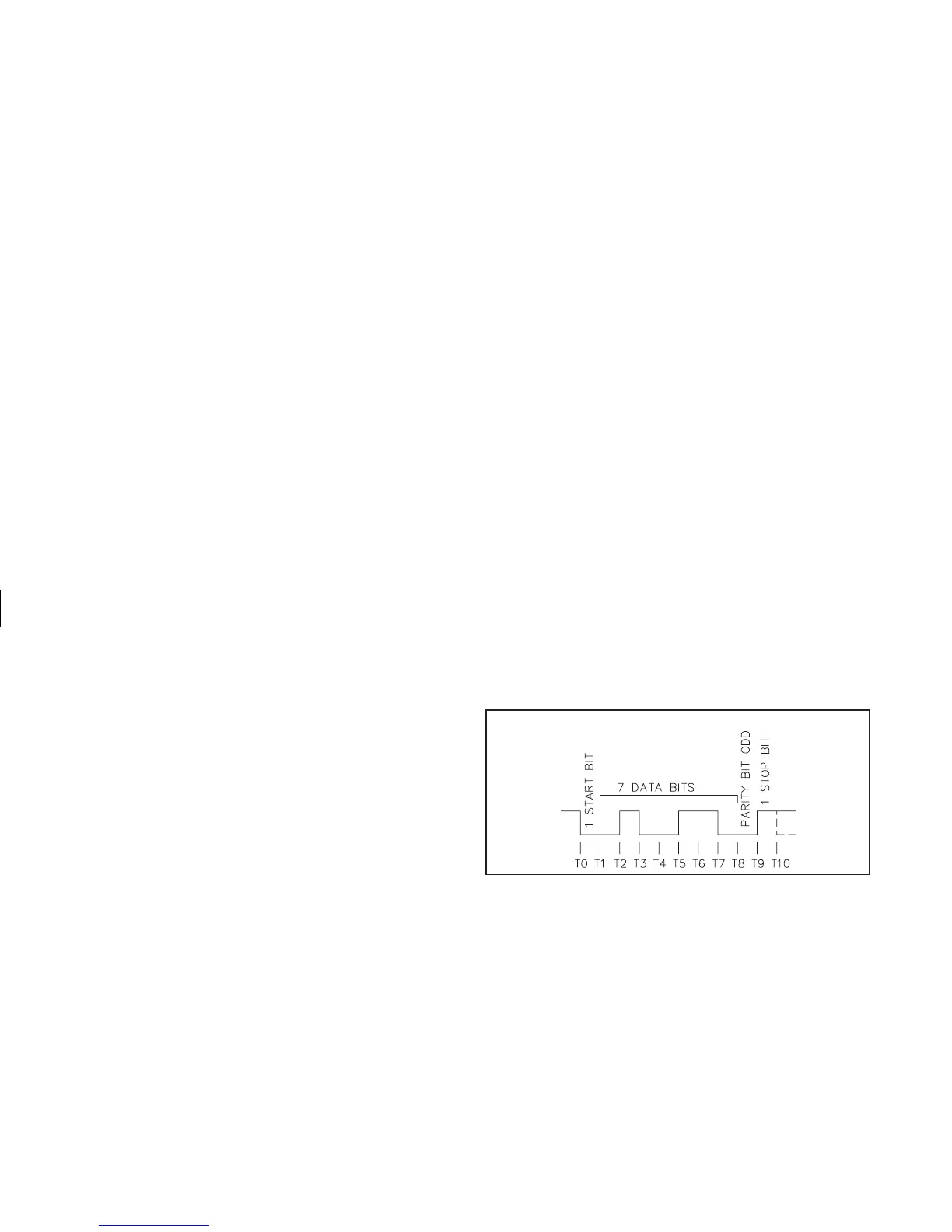
COMMUNICATION FORMAT
Data is sent by switching current on and off in the loop and is received by
monitoring the switching action and interpreting the codes that are transmitted.
In order for data to be correctly interpreted, there must be identical formats and
baud rates among the communicating equipment. The only format available
with this indicator is 1 start bit, 7 data bits, 1 odd parity bit and 1 stop bit. The
baud rates are programmable and the choices are: 300, 600, 1200 and 2400.
Before serial communication can take place, the indicator must be
programmed to the same baud rate as the connected equipment. In addition, the
loop address number, print options and full or abbreviated transmission must be
programmed. If only one indicator is to be used, then a loop address number of
“0” may by used, to eliminate the requirement for the address specifier when
sending a command. If more than one indicator is on the loop, assignment of
unique addresses, other than zero, for each indicator is recommended. Valid
addresses of 0 to 99 may be assigned, but the built-in current source, if used, is
capable of driving up to 7 units. Additional drive capability may be afforded by
an external current source with a higher compliance voltage. Refer to
programming section “Pro 7” to program the serial option.
-30-
DATA FORMAT-10 BIT FRAME [300, 600, 1200, 2400 Baud]