SIGNAL WIRING
Meter signal input common is not isolated from PGM.DIS.,
E1-CON, E2-CON and +EXC. In order to preserve the safety of
the meter application, the signal input common must be limited to
50 V with respect to protective earth ground. If the signal input
common cannot be suitably isolated from protective earth ground
in order to meet this requirement, it must be connected directly to
protective earth ground.
Meter inputs/outputs, other than relay alarms, can not be
connected to operator accessible circuitry when hazardous
live voltage (above 30 V rms, 42.4 V peak) is applied to meter
signal input. Hazardous live circuits should not be accessible
to non-trained personnel.
Interconnection circuitry should not be connected to any user
accessible parts or circuitry.
For Signal Sources Not Requiring Excitation:
Select proper input range jumper. Connect the “+” lead of the process signal
to TBA #6, “+SIGNAL”, and the “-” lead of the signal to TBA #5, “COMM”.
Refer to the transducer manufacturer’s data sheet supplied with the transducer
for proper connections.
Transducers Requiring Excitation:
Select proper input range jumper. Connect the “+” lead of the transducer to
TBA #7, “+EXCITATION”, the “-” lead to TBA #5, “COMM”, and signal
lead to TBA #6, “+SIGNAL”. Refer to the transducer manufacturer’s data
sheet supplied with the transducer for proper connections.
Note: The common of the excitation voltage is connected internally to
“COMM” (TBA #5).
USER INPUT WIRING
User inputs (PGM.DIS., E1-CON, and optional E2-CON) are digital inputs
that are active when connected to TBA #5 Common. Any form of mechanical
switch, sinking collector logic with less than 0.7 V saturation may be used.
The use of shielded cable is recommended. Follow the Additional EMC
Installation Guidelines for shield connection.
OUTPUT WIRING
RELAY CONNECTIONS
To prolong contact life and suppress electrical noise interference due to the
switching of inductive loads, it is good installation practice to install a snubber
across the contactor. Follow the manufacturer’s instructions for installation.
Note: Snubber leakage current can cause some electro-mechanical devices to
be held ON.
SELECTING THE INPUT RANGE
To select or change the input range the following steps apply:
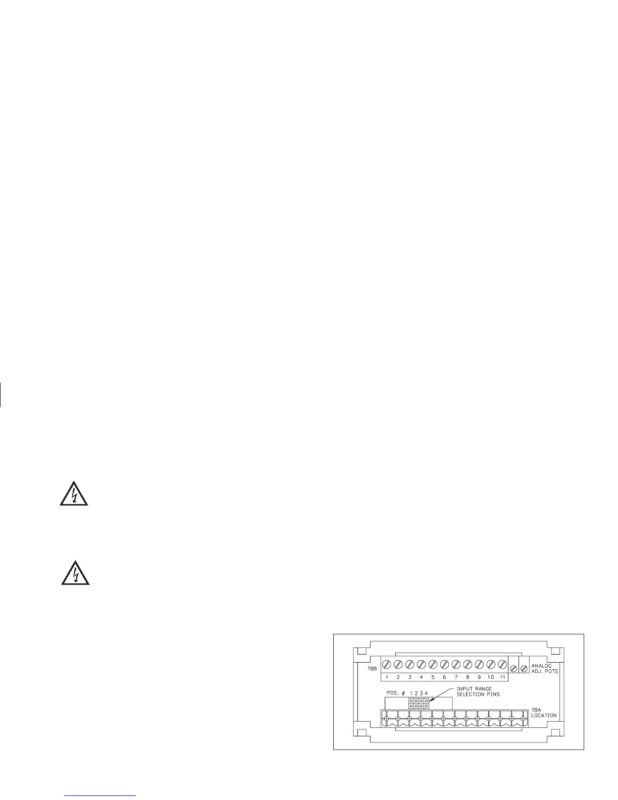
1. Remove terminal block “A” (TBA).
2. Using a pair of long nose pliers, remove the jumper and re-position it in the
location corresponding to the range being selected. (When the unit is
shipped from the factory, the jumper is in position #4.)
Looking at the rear of the unit, the position numbers and their
corresponding ranges are as follows, from left to right:
POSITION #1 ±2 VDC
POSITION #2 ±20 VDC
POSITION #3 ±200 VDC
POSITION #4 ±300 VDC
3. Replace terminal block “A” (TBA). Input range selection is now complete.
Although the unit has been factory calibrated for all ranges, greater
accuracy can be achieved by calibrating the individual range in use.
(Refer to “PRO 1” for scaling)
-41-
REAR VIEW OF IMD1 WITH TBA TERMINALS REMOVED