WIRING CONNECTIONS
After the unit has been mechanically mounted, it is ready to be wired. All
conductors should meet voltage and current ratings for each terminal. Also
cabling should conform to appropriate standards of good installation, local
codes and regulations. It is recommended that power supplied to the unit (AC or
DC) be protected by a fuse or circuit breaker. All wiring connections are made
on removable plug-in terminal blocks. There is a separate terminal block for the
bottom board (TBA) and optional top board (TBB). When wiring the unit,
remove the terminal block and use the numbers on the label to identify the
position number with the proper function. Strip the wire, leaving approximately
1/4" bare wire exposed (stranded wires should be tinned with solder). Insert the
wire into the terminal and tighten down the screw until the wire is clamped
tightly. Each terminal can accept up to one 14-gage, two 18-gage or four
20-gage wire(s). After the terminal block is wired, install it into the proper
location on the PC board. Wire each terminal block in this manner.
POWER WIRING
Primary AC power is connected to TBA #1 and 2 (marked VAC 50/60 Hz,
located on the left hand side of the bottom terminal block). To reduce the
chance of noise spikes entering the AC line and affecting the indicator, the AC
power should be relatively “clean” and within the specified ±10% variation
limit. Drawing power from heavily loaded circuits or circuits which also
power loads that cycle on and off, (contactors, relays, motors, machinery,
etc.) should be avoided.
-40-
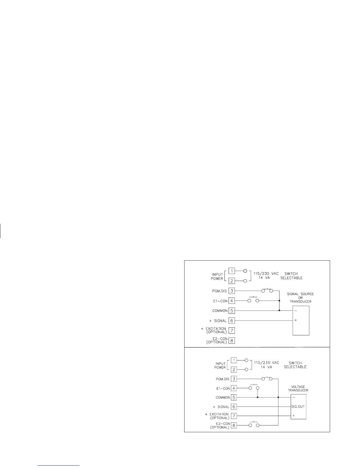
A.C. Power Basic Connection
A.C. Power Connection w/Internal 18 v Excitation