DC IN
Use the DC IN port to provide power to the camera system. When power is applied to the DC IN port, Aux Power is
available from the module, and the attached battery may be charged.
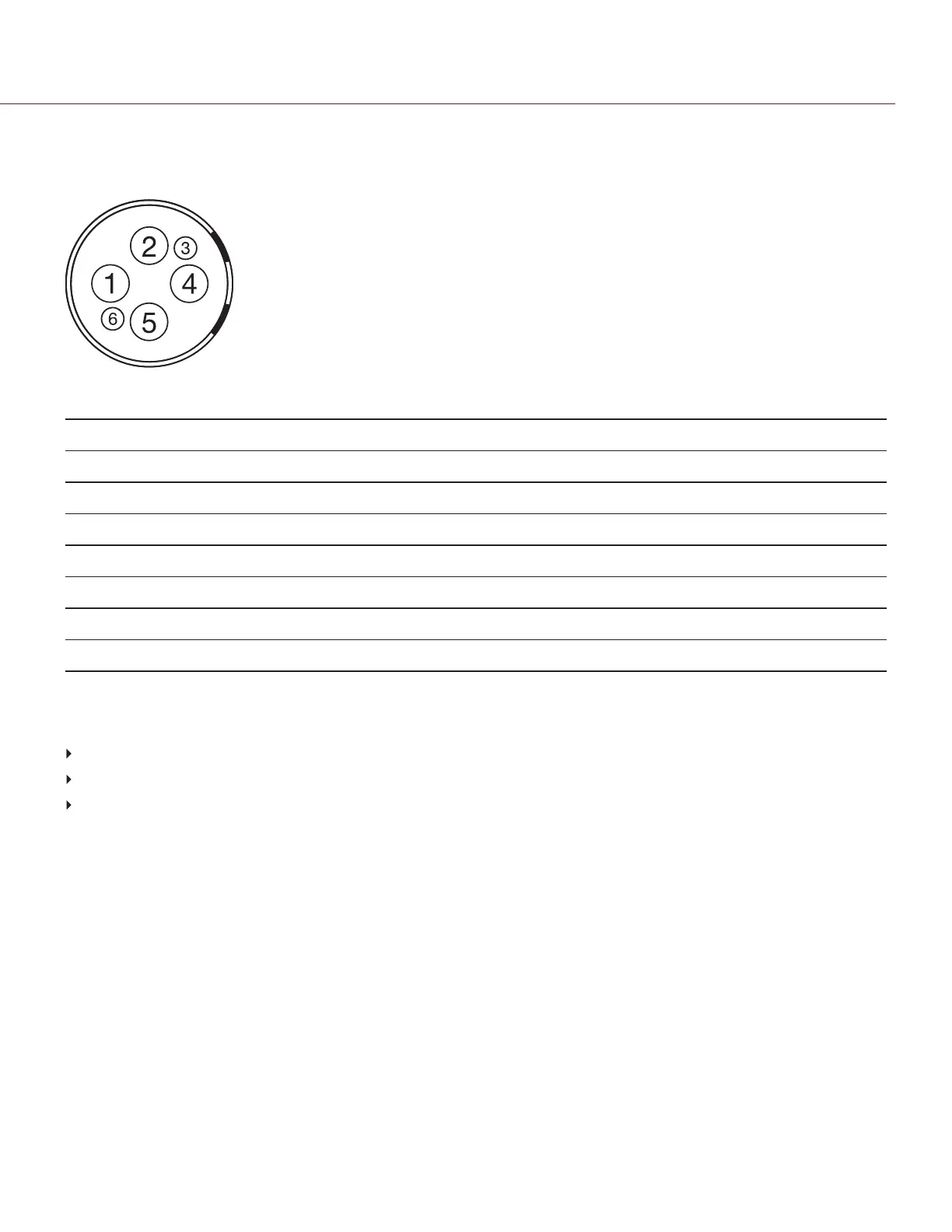
Figure: Front Face of DC IN Connector
6-PIN 1B LEMO DC IN CONNECTOR
PIN SIGNAL DESCRIPTION DIRECTION
1 +VBATT Power input, +11.5 to +17 VDC Out
2 +VBATT Power input, +11.5 to +17 VDC Out
3 SCL-BATT Serial battery bus clock Out
4 GROUND Power return (camera ground) Out
5 GROUND Power return (camera ground) Out
6 SDA-BATT Serial battery bus clock Out
NOTE: Mating connector is FGJ.1B.306.CWLD72Z.
COMPATIBLE CABLES
790-0138: RED 2B-to-1B LEMO Power Adaptor Cable
790-0164: XLR Power Cable (10')
790-0165: XLR Power Cable (30')
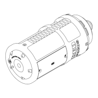
INSTALL THE DSMC2 V-LOCK BATTERY MODULE PRO
REQUIRED TOOL(S): T20 TORX driver
1. Turn off the camera.
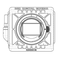
2. Position the module on the rear of the camera or expander, aligning the connector on the front of the module with
the connector on the rear of the camera or expander.
3. Apply pressure and tighten the four (4) captive screws in a cross pattern (“X” pattern) approximately two (2) turns
each using a T20 TORX driver. DO NOT FULLY TIGHTEN.
4. Fully tighten the four (4) screws in a cross pattern (“X” pattern) using a T20 TORX driver.
WARNING: DONOTOVERTIGHTEN.
C OPYRI G HT © 2017 RED.C OM , LLC 955- 0038, REV-AD| 58
RED DSMC POWER OPERATION GUIDE