COPYRIGHT © 2014 RED.COM, INC
RED DSMC OPERATION GUIDE
955-0020_V5.1, REV-H | 122
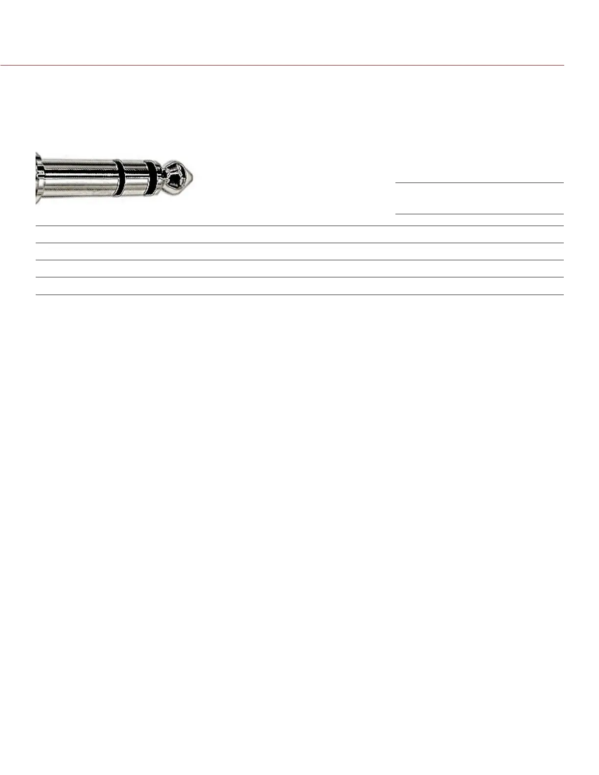
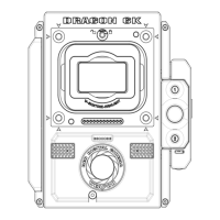
MIC-1, MIC-2 (MICROPHONE AUDIO)
Two 3.5mm phone jacks on the front of the BRAIN support two independent channels of balanced or unbal-
anced microphone level analog audio inputs.
Nominal input impedance for each microphone jack is 2.4K ohm.
PIN SIGNAL DESCRIPTION DIRECTION
TIP IN + Mic Input (+48V Phantom Power) In
RING IN - Mic Input (+48V Phantom Power) In
SLEEVE GND Camera ground N/A
Microphone Level analog audio input signals are routed via a high quality pre-amplifier and soft limiter, whose
Gain may be controlled using the Input Level control to achieve the desired audio reference/recording level.
Microphone inputs support +48V @ 10mA Phantom Power as a user selectable option.
To assist with reference level setup, the camera provides a color-coded Peak Level Meter in the Graphical User
Interface, with witness marks that indicate 0 dBu (-20 dBFS) and 0 VU (-16 dBFS) levels.
Peak Level Meter range is –36 dBu to +20 dBu (-54 dBFS to 0 dBFS) and provides input clip indication.
NOTE: A pre-fabricated XLR to TRS interface cable, the XLR MICROPHONE CABLE (P/N 790-0229), is available
from RED Digital Cinema.
Microphone Input Connector