COPYRIGHT © 2014 RED.COM, INC
RED DSMC OPERATION GUIDE
955-0020_V5.1, REV-H | 28
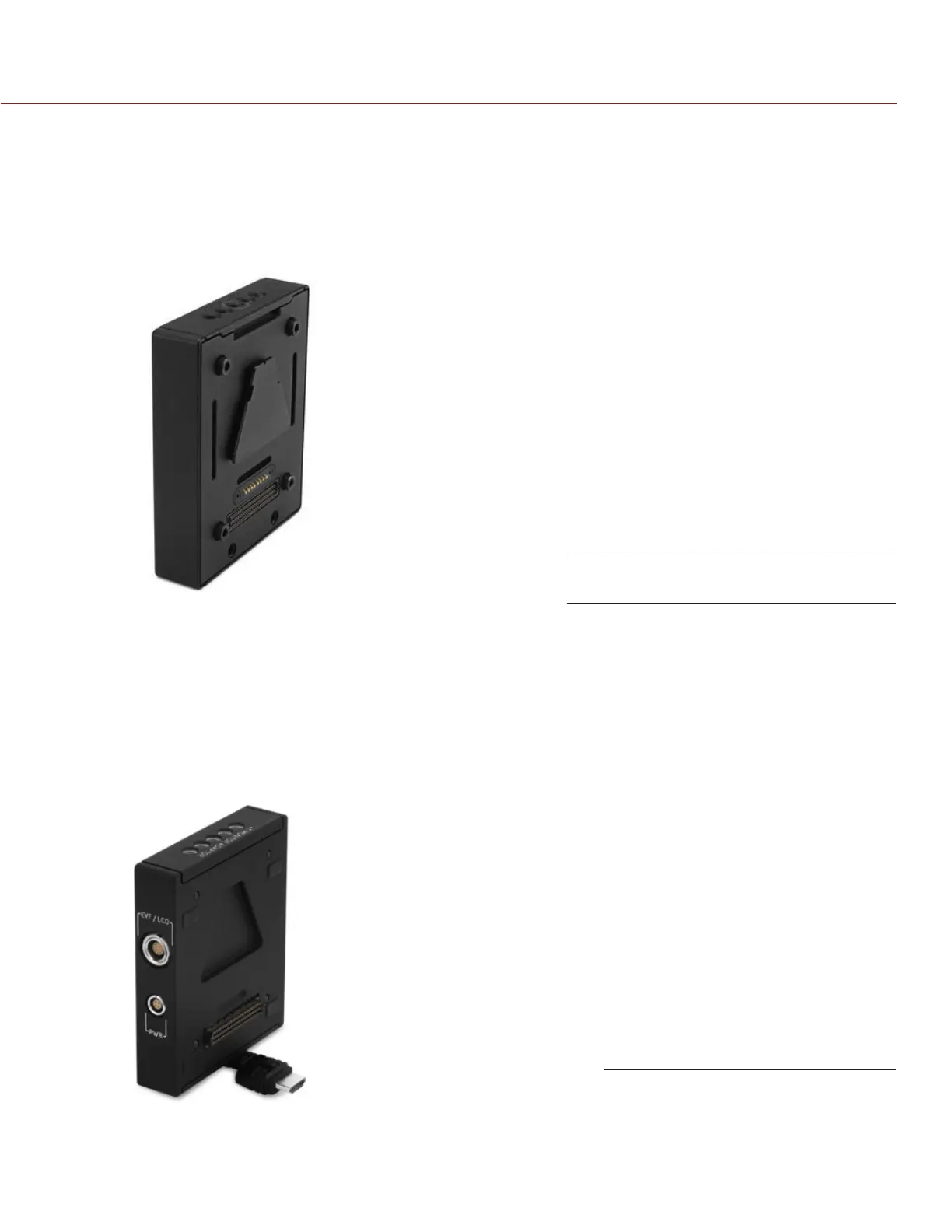
MODULE ADAPTOR
The MODULE ADAPTOR enables DSMC modules to connect the DSMC BRAIN for expandable functionality.
The MODULE ADAPTOR features additional ¼-20 mounting points on top for further add-ons and configuration
support. Most RED DSMC modules require a MODULE ADAPTOR or +1 ADAPTOR MODULE to attach to your
DSMC BRAIN.
WARNING: MODULE ADAPTOR is NOT compatible with the +1 ADAPTOR MODULE.
WARNING: The MODULE ADAPTOR IS NOT compatible with the +1 ADAPTOR MODULE.
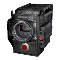
+1 ADAPTOR MODULE
The +1 ADAPTOR MODULE mounts onto the back of a DSMC BRAIN and provides power and support for an
additional RED EVF/LCD. The +1 ADAPTOR MODULE also includes an AUX power port for 4-pin third party ac-
cessories. Other 2-pin accessories are also compatible when using a 4-PIN TO 2-PIN ADAPTOR CABLE.
WARNING: The +1 ADAPTOR MODULE IS NOT compatible with the MODULE ADAPTOR.
WARNING: DO NOT use the EVF/LCD port if a PRO I/O MODULE is connected to the DSMC BRAIN.
NOTE: The +1 ADAPTOR MODULE requires DSMC firmware v4.0.8 or later.
MODULE ADAPTOR
+1 ADAPTOR MODULE