919-575 5/19/15
E33-10
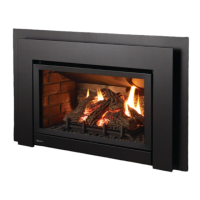
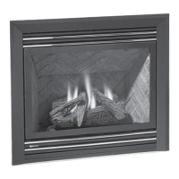
OPTIONAL VIGNETTE FACEPLATE INSTALLATION
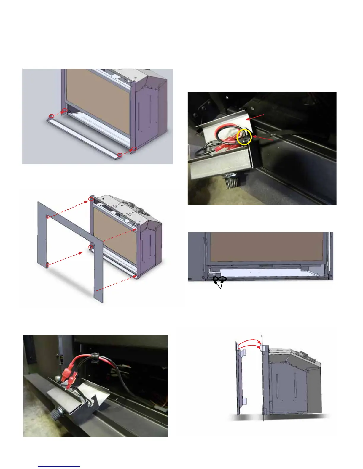
2. Install 3 sided/4 sided vignette faceplate to the unit with 2 screws each
on top and bottom as shown in the picture below..
4. Tuck the wires into the silver box and secure them with a
small grommet.
5. Bend the silver cover to close the box.
Grommet
Silver cover
3. Connect the male end black and red fan switch wires (in the silver box)
to the wires connectors from the fan speed control box .
6. Install the fan speed control box to the left side of the unit (when
facing the front of the unit) with 2 screws. Refer to the picture
below. .
7. Install the safety screen to the unit.
Tighten these 2 screws
3 sided Vignette
Faceplate shown
1. Install the lower trim to the unit with 2 screws on each side as shown
in the drawing below.