E33-10 FPI Direct Vent Gas Insert | 37
|
37
maintenance
11) Disconnect the inlet gas line.
12) Unplug the black and red wires at the valve.
Undo the 2 TP wires at the valve.
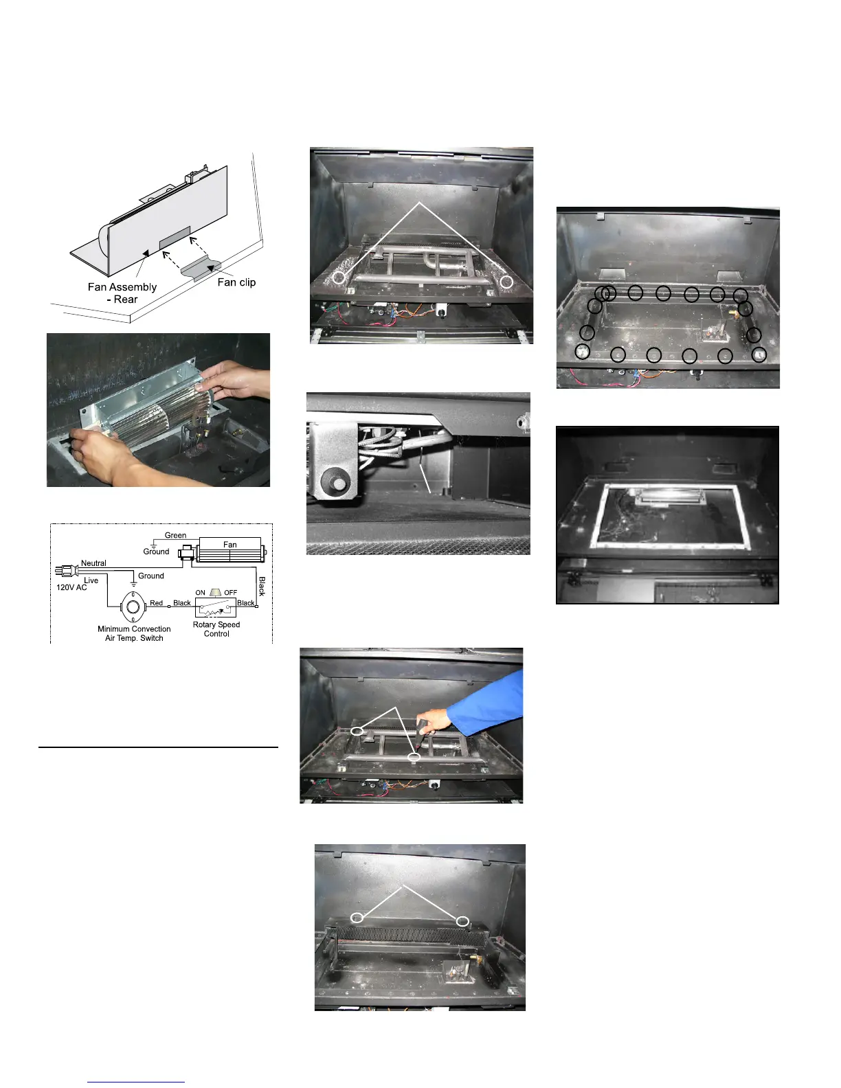
13) Remove the 17 screws on the valve tray.
14) Take out the valve tray from the unit.
15) Scrape o the old gasket from the oor of the
rebox and from the valve access plate.
16) Install new gasket and valve assembly (reverse
steps 9-14).
NOTE: Failure to install a new gasket may
severely aect the appliance performance.
17) Hook up gas line and check for gas leaks with
soap and water solution or a gas leak detector.
Do not use open ame for leak testing.
18) Set up the air shutter to 5/16" for NG and 7/16"
for LP.
19) Fire up the unit temporarily.
20) Check the manifold pressure 3.8" W.C. for NG
and 11" W.C. for LP.
21) Reverse steps 4-8.
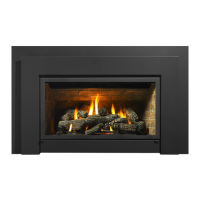
Replacing fan:
14) Reverse above steps.
Seal fan access panel using high temperature
silicone (sparingly).
12) Pull Fan Assembly forward, to disengage the fan
clip on the rear wall. Then lift the Fan Assembly
up and pull through rebox opening.
13) Disconnect green wire from power cord.
1) Turn the unit o and allow it to cool down to
room temperature.
2) Unplug or disconnect power source.
3) Shut o the main gas supply.
4) Remove the safety screen and glass door.
5) Remove logs and grate.
6) Remove optional brick set, if installed.
VALVE ASSEMBLY
REMOVAL AND
INSTALLATION
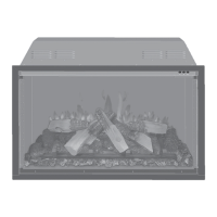
7) When removing base brick sides the two screws
that hold the grate down must be removed rst.
Straighten adjustment wire.
Air Shutter Wire
9) Remove the Burner by removing the 2 screws
(1 on burner bracket and one on valve tray).
Tilt the burner up and slide to the left away from
the orice.
8) Straighten the adjustment wire under the rebox
base.
Screws
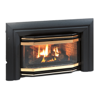
10) Remove the rear log support by unscrewing
the 2 screws.
Screws
Screws