32 | E33-10 FPI Direct Vent Gas Insert
|
32
installation
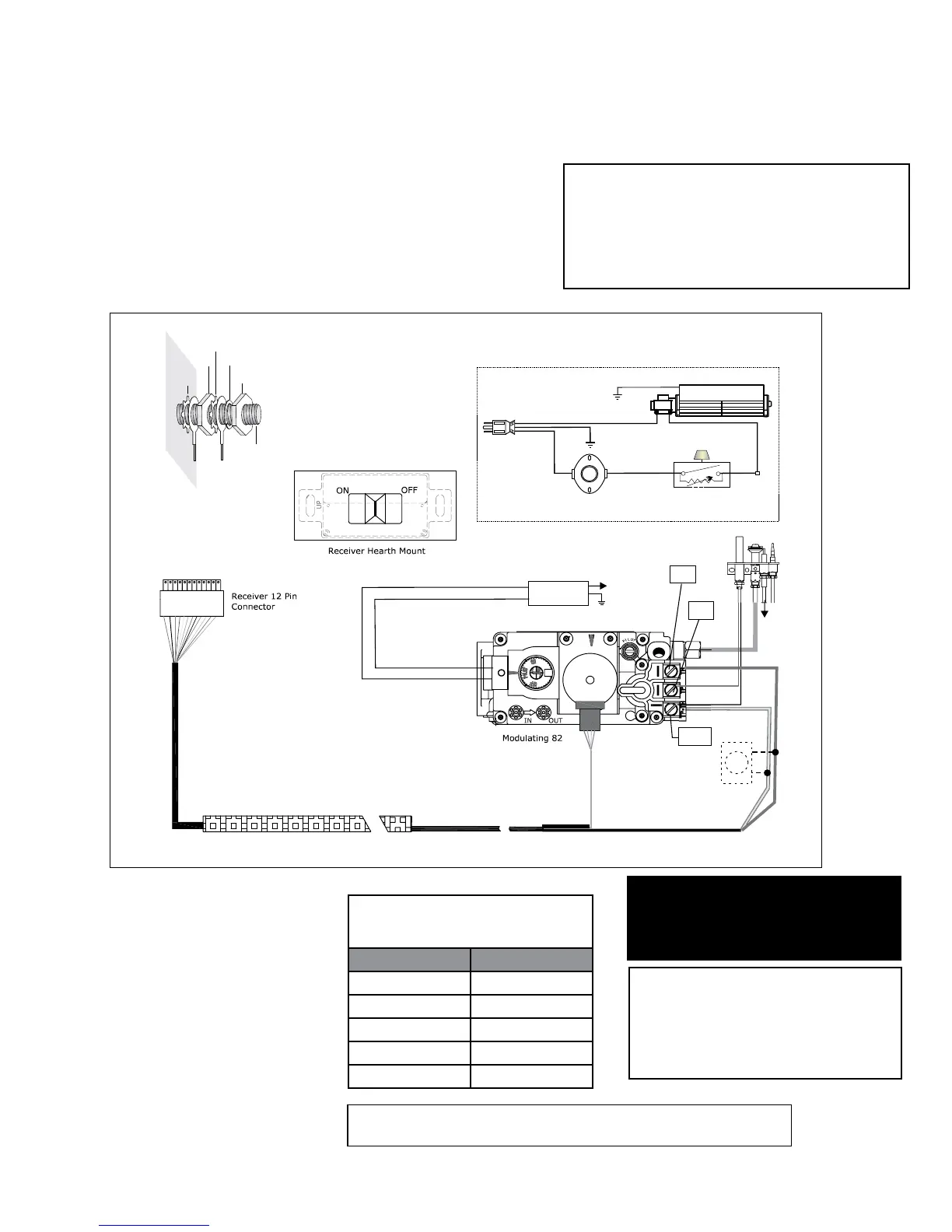
WIRING DIAGRAM
This heater does not require a 120V A.C. supply
for operation. However, a 120V A.C. power
supply is needed for the fan/blower operation.
WARNING: Electrical Grounding Instructions
This appliance is equipped with a three pronged
(grounding) plug for your protection against shock
hazard and should be plugged directly into a
properly grounded three-prong receptacle. Do not
cut or remove the grounding prong from this plug.
Caution: Ensure that the
wires do not touch any hot
surfaces and are away from
sharp edges.
CAUTION: Label all wires prior
to disconnection when servicing
controls. Wiring errors can cause
improper and dangerous operation.
ENGLISH
REMOTE
TP
TH
TPTH
Green
White
Red
Black
(+)
(-)
9
Ground
Neutral
Live
Black
Black
Red
Minimum Convection
Air Temp. Switch
ON OFF
Rotary Speed
Control
120V AC
60 Hz
Green
Ground
Fan
Lockwasher
Fan
ground
Power
cord
ground
wire
Star
washer
Nut
Nut
#8 Ground Lug
Star
washer
DC
Spark Box
To
Electrode
To
Electrode
Thermostat
(Optional)
(Millivolt)
Optional
Wall Thermostat
A wall thermostat may be installed if desired,
connect the wires as per the wiring Diagram.
Use table to determine the maximum wire length.
Note: Preferable if the thermostat is
installed on an interior wall.
Regency
®
oers an optional programmable
thermostat but any 250-750 millivolt rated non-
anticipator type thermostat that is CSA, ULC or
UL approved may be used.
Thermostat Wire Table
Recommended Maximum Lead Length
(Two-Wire) When Using Wall
Thermostat (CP-2 System)
Wire Size Max. Length
14 GA. 50 Ft.
16 GA. 32 Ft.
18 GA. 20 Ft.
20 GA. 12 Ft.
22 GA. 9 Ft.
CAUTION
Do not wire millivolt
wall thermostat wires
to 120V wire.
NOTE: When the wall thermostat is connected, the remote control transmitter
and all of its features are now disabled.