10 | Regency Ultimate
™
U1500E Gas Fireplace
installation
This includes:
1. Clocking the appliance to ensure the correct
firing rate (rate noted on label 43,000 Btu/h
(NG), 42,000 Btu/h (LP) after burning appliance
for 15 minutes.
2. If required, adjusting the primary air to ensure
that the flame does not carbon. First allow the
unit to burn for 15-20 min. to stabilize.
CAUTION: Any alteration to the product that
causes sooting or carboning that results in dam-
age is not the responsibility of the manufacturer.
INSTALLATION CHECKLIST
1. Locate appliance
a) Room location (Refer to "Locating Your Gas
replace" section)
b) Clearances to Combustibles (Refer to
"Clearances" section)
c) Mantel Clearances (Refer to "Mantel
Clearances" section)
d) Framing & Finishing Requirements (Refer
to "Framing & Finishing" section)
e) Venting Requirements (Refer to "Venting"
section)
2. Position nailing strips (Refer to "Unit Assembly
Prior to Installation).
3. Slide unit into place.
4. Remove installation access panel.
5. Install vent (Refer to "Venting Arrangement"
sections).
6. Make gas connections (Refer to "Gas Line
Installation section).
7. Make electrical connections to receptacle
supplied with unit (recommended).
8. Install batteries into the transmitter. Batteries
should not be installed into the battery holder/
switch box if electrical connections are made
to the receptacle. They can be installed during
power outages to run the main burner.
9. See remote control instructions for operation
of this device.
10. Test the pilot (Refer to "Pilot Adjustment" section).
11. Test Gas Pressure (Refer to "Gas Pipe Pressure
Testing" section).
12. Install standard and optional features. Refer to
the following sections:
a) Log Install
b) Inner Door Frame
c) Outer Faceplate/Verona surround
d) Finishing Trim
e) Enamel panels
f) Heatwave kit
13. Reinstall installation access panel.
14. Final check.
Before leaving this unit with the customer, the
installer must ensure that the appliance is ring
correctly and operation fully explained to
customer.
LOCATING YOUR
GAS FIREPLACE
1. When selecting a location for your fireplace,
ensure that the clearances are met.
2. The appliance must be installed on a flat, solid,
continuous surface For example a wood, metal
or concrete floor or in a raised (on the wall) ap-
plication. The appliance must be installed on
a metal or wood panel extending the full width
and depth of the appliance.
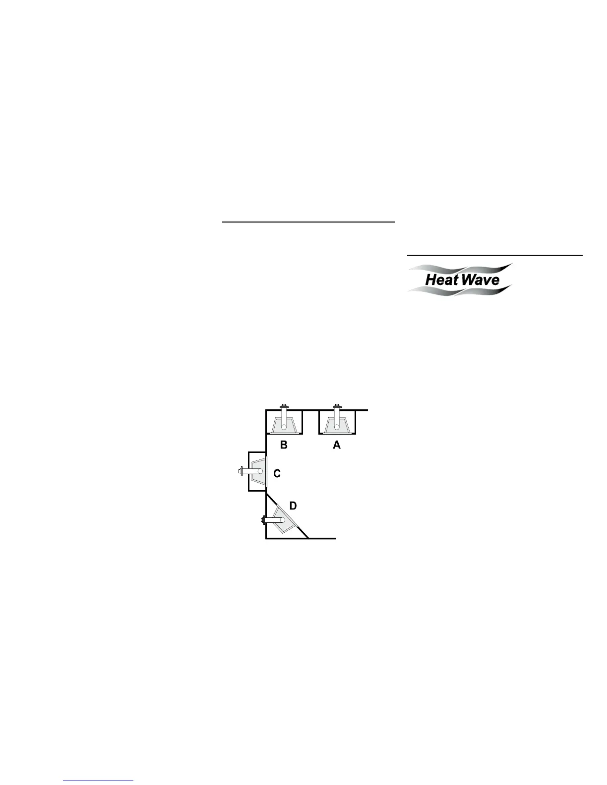
3. The U1500E Direct Vent Gas Fireplace can be
installed in a recessed position or framed out
into the room as in A, B, C and D.
See Diagram 1.
Diagram 1
A) Flat on Wall
B) Flat on Wall Corner
C) Recessed into Wall/Alcove
D) Corner
4. This appliance is Listed for bedroom installations
using the standard Remote (thermostat system).
Some areas may have further requirements,
check local codes before installation.
5. The U1500E Direct Vent Gas Fireplace
is approved for alcove installations, see
"Clearances" section for details.
6. We recommend that you plan your installation on
paper using exact measurements for clearances
and floor protection before actually installing
this appliance. Have an authorized inspector,
dealer, or installer review your plans before
installation.
Note: For vent terminations refer to "Exterior
Vent Termination Locations" section.
HEATWAVE
DUCT SYSTEM
OPTIONAL KIT
The HeatWave Air Duct Kit increases the
eectiveness of your replace by dispersing warm
air from the replace to remote locations in the same
room or other rooms in your home.
Up to two kits may be installed on the replace.
Please Note: Only 1 HeatWave kit may be operated
at one time. This includes the internal blower as well.
The HeatWave Duct Kit has dierent clearance
and framing requirements, check the HeatWave
manual for details.