Renesas RA Family MCK-RA6T2 User's Manual
R12UZ0091EJ0100 Rev 1.00 Page 20 of 38
August 3, 2021
5. Inverter Board Specification
This section describes inverter board specification.
5.1 Functions
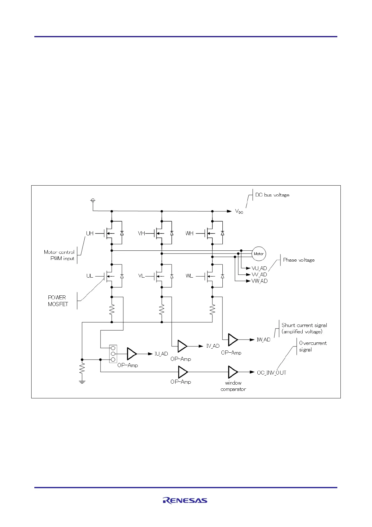
5.1.1 Inverter control circuit block
The inverter board has the inverter control circuit block which controls the motor with 6 POWER MOSFETs.
POWER MOSFET is controlled with 6-phase timer output of MCU.
The inverter control circuit block outputs DC bus voltage, U, V and W phase voltage and shunt current to the
connectors (CN3, CN4). By inputting these output voltages to A/D of MCU on the CPU card, analog values of
the voltage and the shunt current of each phase can be measured. Refer to 5.1.2 and 5.1.4 for the current
detection and the voltage detection, respectively. Also function to detect overcurrent from the input current is
available. Refer to 5.1.3 for details.
An illustration of the inverter control circuit block is shown in Figure 5-1. In the actual circuit, some inputs on
the A/D pins are via voltage dividers and offsets and so on. Refer to the circuit diagram for details.
Figure 5-1 Illustration of inverter control circuit block

 Loading...


