Renesas RA Family MCK-RA6T2 User's Manual
R12UZ0091EJ0100 Rev 1.00 Page 21 of 38
August 3, 2021
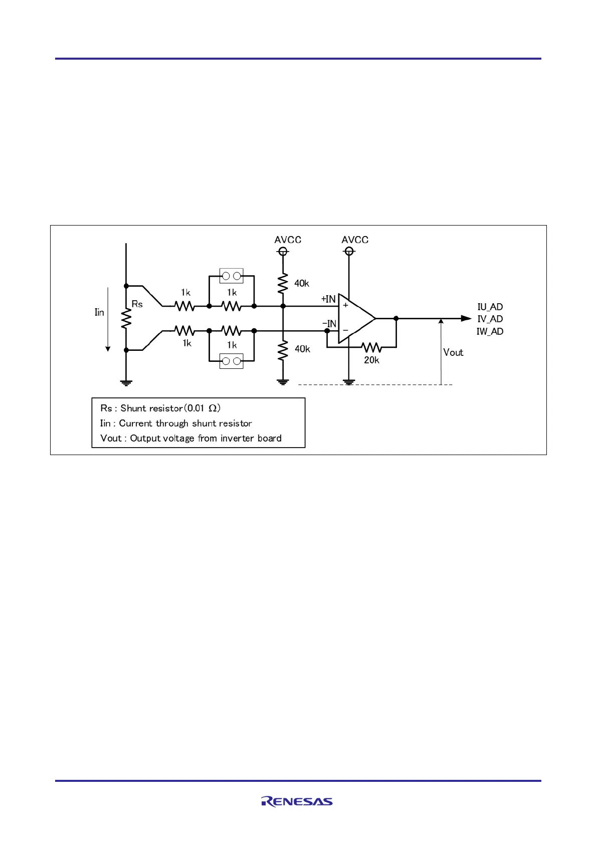
5.1.2 Current detection circuit
The inverter board has the current detection circuit to measure the current at the U, V and W phase. The
current detection circuit uses shunt resistor at each phase. Voltage drop caused by the current flowing
through the shunt resistor is amplified by the current detection amplifier to output. The default gain of the
current detection amplifier is set to 20x, but the gain can be changed to 10x by setting JP5, JP7, JP9, JP10,
JP14, and JP15 to open. The relationship between the current Iin flowing through the shunt resistor and the
voltage Vout output from the current detection circuit is shown in equations (1) and (2). In addition, by
switching JP8 and JP11 to 2-3 pin short circuit, one shunt current detection can be supported.
Amplifier gain 10x : Ω (1)
Amplifier gain 20x : Ω (2)
Figure 5-2 Current detection circuit

 Loading...


