Renesas RA Family MCK-RA6T2 User's Manual
R12UZ0091EJ0100 Rev 1.00 Page 22 of 38
August 3, 2021
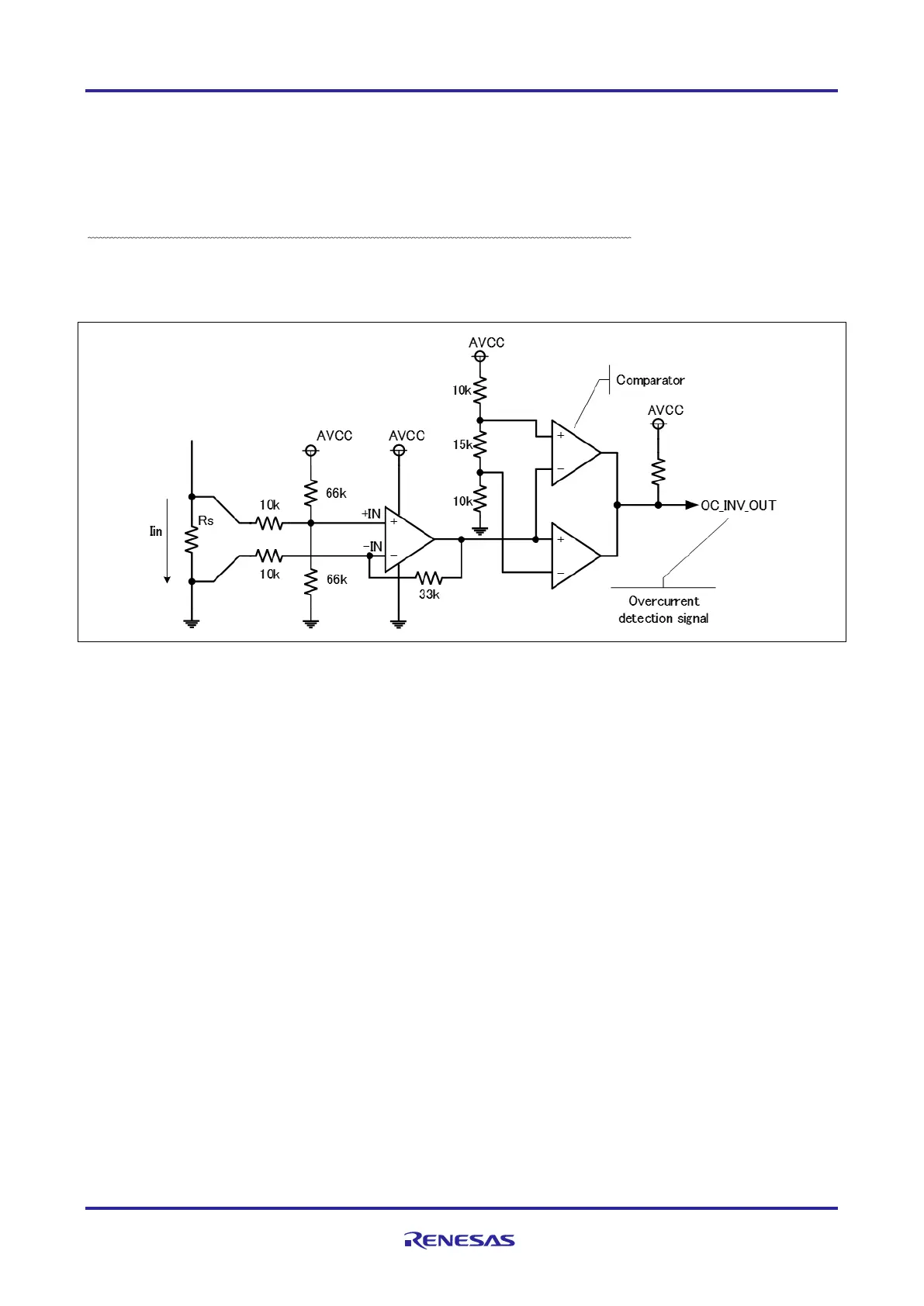
5.1.3 Overcurrent detection circuit
Detect the overcurrent from the input current, using the overcurrent detection circuit illustrated in Figure 5-3.
If the current value is within the range of threshold, OC_INV_OUT is HIGH, and this changes to LOW if
overcurrent is detected. Therefore, you can protect the board and motor by monitoring the over current
detection signal and setting PWM signals for gate driver to LOW or Hi-Z if the over current detection signal
changes to LOW.
The overcurrent detection circuit does not directly protect the board and motor. Protect them by performing
appropriate processing with equipment such as microcontroller.
Figure 5-3 Overcurrent detection circuit

 Loading...


