EasyManuals Logo
Home>Renesas>Motherboard>RA6 Series

Renesas RA6 Series User Manual

Renesas RA6 Series
44 pages
To Next Page IconTo Next Page
To Previous Page IconTo Previous Page
Page #34 background imageLoading...
Page #34 background image
Renesas RA Family MCK-RA6T2 User's Manual
R12UZ0091EJ0100 Rev 1.00 Page 31 of 38
August 3, 2021
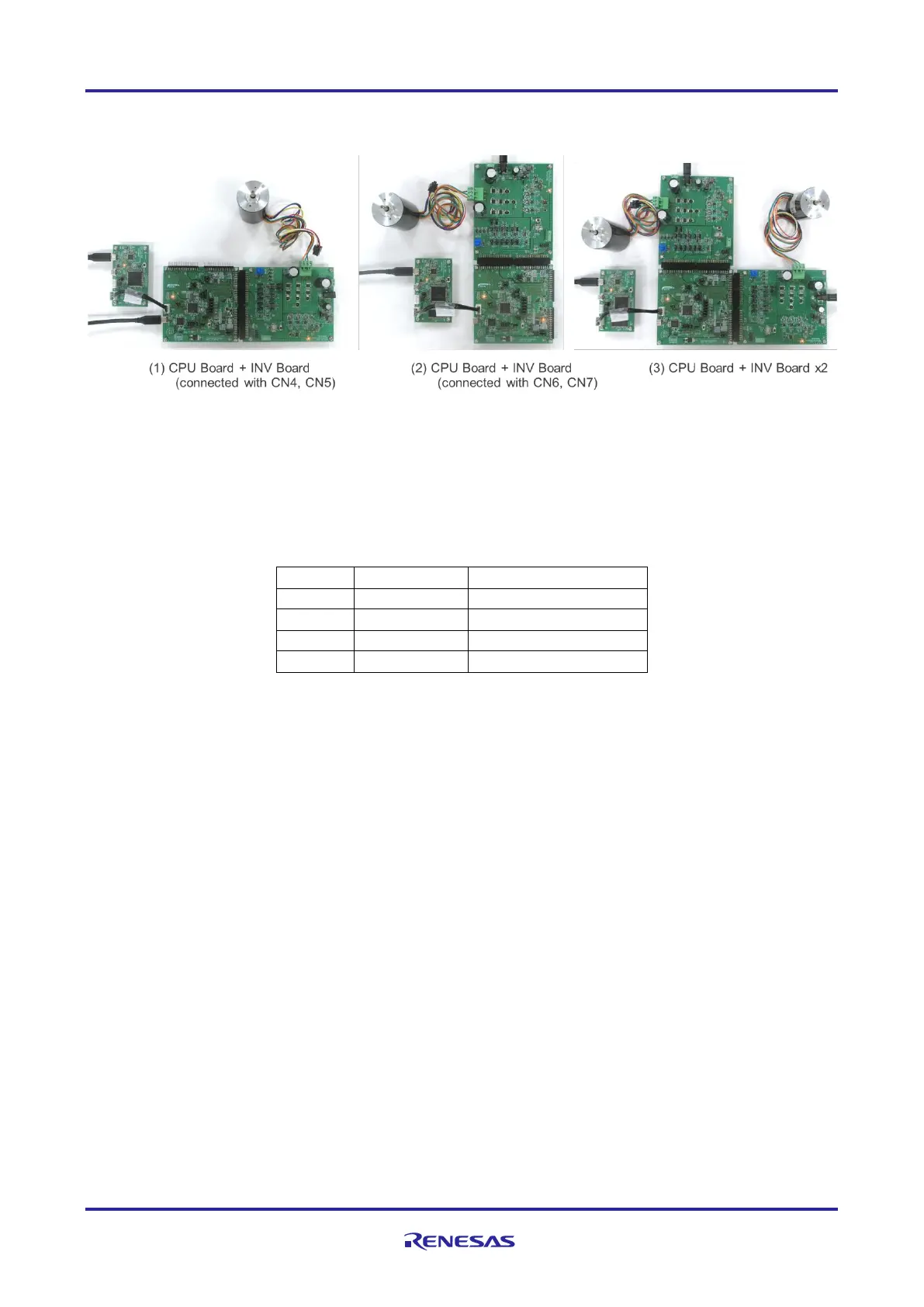
The connection for CPU board and inverter board is shown in Figure 6-1. Please refer to 4.6.2 for the power
supply method.
Figure 6-1 Connection for CPU board and inverter board
6.1.4 Serial communication
For serial communication using Renesas Motor Workbench, the CPU board has SCI connector. Pin
assignment for SCI connector is listed in Table 6-5.
Table 6-5 SCI connector (CN10) pin assignment
Pin No.
Pin Function
RA6T2 Connection Pin
1
VCC
-
2
MCU TXD
PD05/TXD9_A
3
MCU RXD
PD06/RXD9_A
4
GND
-
6.1.5 Reset circuit
This product has a reset circuit to enable power-on reset or external reset on MCU. Push the tact switch
(SW1) to externally reset MCU.

Other manuals for Renesas RA6 Series

Questions and Answers:

Question and Answer IconNeed help?

Do you have a question about the Renesas RA6 Series and is the answer not in the manual?

Renesas RA6 Series Specifications

General IconGeneral
BrandRenesas
ModelRA6 Series
CategoryMotherboard
LanguageEnglish

Related product manuals