EasyManuals Logo
Home>Renesas>Motherboard>RA6 Series

Renesas RA6 Series User Manual

Renesas RA6 Series
44 pages
To Next Page IconTo Next Page
To Previous Page IconTo Previous Page
Page #28 background imageLoading...
Page #28 background image
Renesas RA Family MCK-RA6T2 User's Manual
R12UZ0091EJ0100 Rev 1.00 Page 25 of 38
August 3, 2021
5.2 Pin assignment
5.2.1 CPU board connector
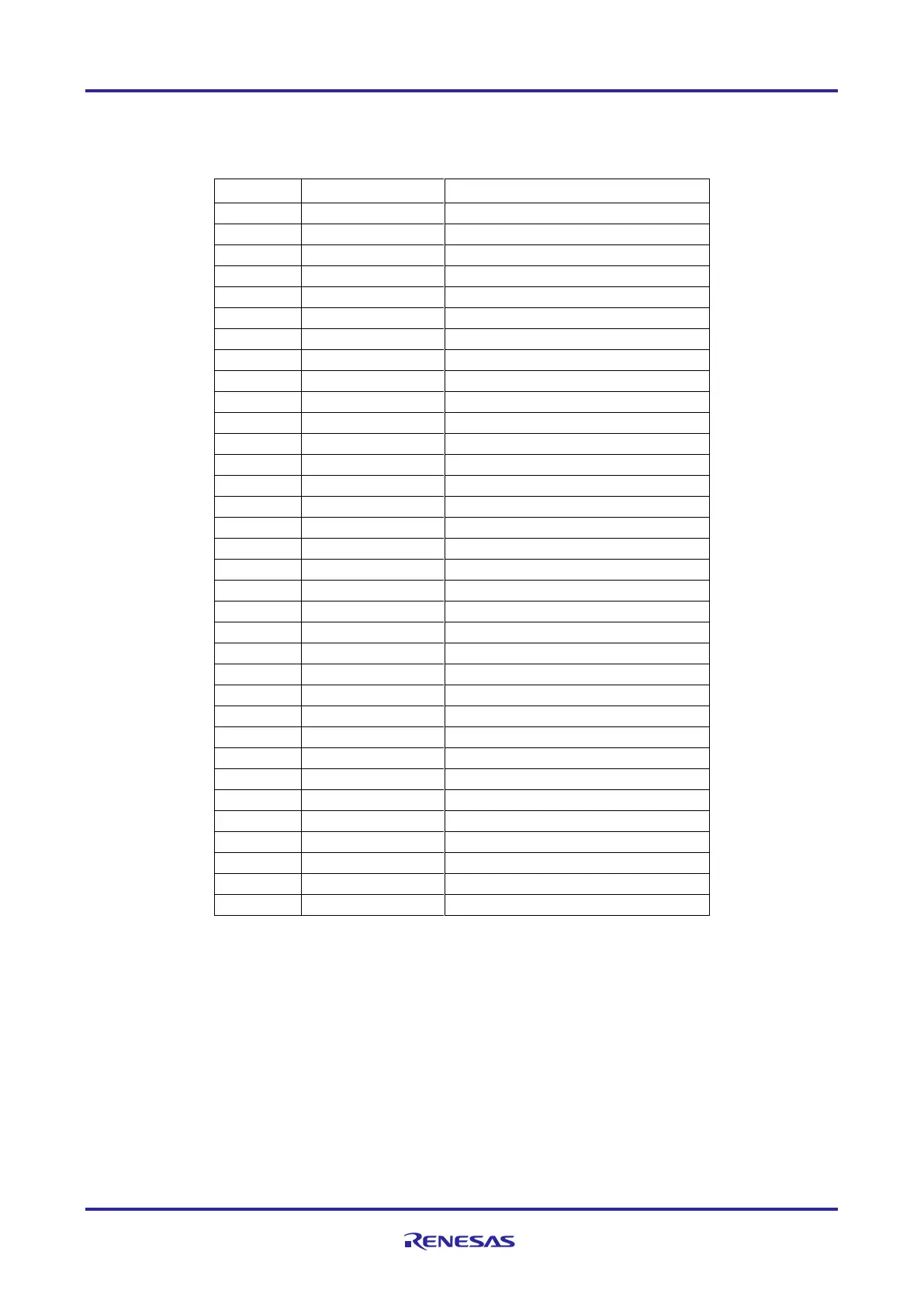
Table 5-5 CPU board connector (CN3)
Pin No.
Output direction
Signal
1
-
SPARE1
2
-
AGND
3
To CPU
DC bus voltage detection
4
-
AGND
5
To CPU
U-phase current detection
6
To CPU
U-phase current detection (PGAVSS)
7
To CPU
V-phase current detection
8
To CPU
V-phase current detection (PGAVSS)
9
To CPU
W-phase current detection
10
To CPU
W-phase current detection (PGAVSS)
11
To CPU
U-phase voltage detection
12
To CPU
V-phase voltage detection
13
To CPU
W-phase voltage detection
14
-
AGND
15
To CPU
VPFC_AD
16
To CPU
IPFC_AD
17
To CPU
VR1
18
-
AGND
19
-
AVCC
20
-
AVCC
21
-
AGND
22
-
AGND
23
-
VCC
24
-
VCC
25
-
DGND
26
-
DGND
27
To INV
PWM U-phase (Lower)
28
-
DGND
29
To INV
PWM U-phase (Upper)
30
-
DGND
31
To INV
PWM V-phase (Lower)
32
-
DGND
33
To INV
PWM V-phase (Upper)
34
-
DGND

Other manuals for Renesas RA6 Series

Questions and Answers:

Question and Answer IconNeed help?

Do you have a question about the Renesas RA6 Series and is the answer not in the manual?

Renesas RA6 Series Specifications

General IconGeneral
BrandRenesas
ModelRA6 Series
CategoryMotherboard
LanguageEnglish

Related product manuals