TPS-1 User’s Manual: Hardware 3. Host Interface
R19UH0081ED0107 Rev. 1.07 page 19 of 86
Jul 30, 2018
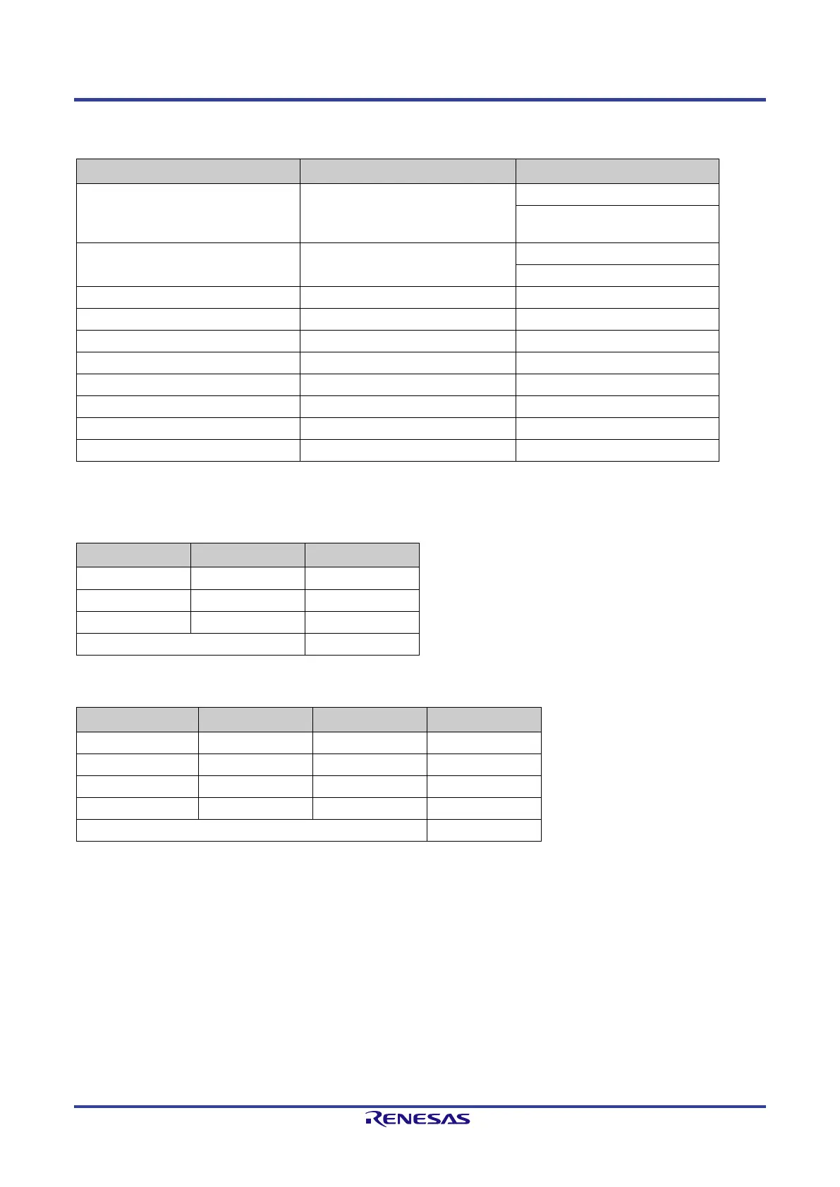
Table 3-2 describes all signals of the parallel Host interface.
Table 3-2: Parallel Host Interface Layout
Signal designation Function Remarks
LBU_WR_EN_IN Write Control active low (Intel mode)
(Motorola mode)
LBU_READ_EN_IN Read Control active low (Intel-mode)
no function (Motorola-Mode)
LBU_CS_IN Chip Select
LBU_BE_2_IN Byte Selection 2
LBU_DATA0 – LBU_DATA15 data line 0 – 15
LBU_SEG0_IN Low Bit of the segment page selection
During a memory access, the TPS-1 behaves like a „16-bit Little Endian“ device with an 8-bit or 16-bit memory. The possible access types are listed in
Table 3-3.
Table 3-3: 16-Bit External Host Databus
LBU_BE_2_IN LBU_BE_1_IN Access type
1 0 8-Bit LOW
0 0 16-Bit
Table 3-4: 8-Bit External Host Databus
LBU_A[1:0] LBU_BE_2_IN LBU_BE_1_IN Access type
00 1 0 8-Bit access
10 1 0 8-Bit access
Other combinations Not allowed
An illegal access results in an „Error-IRQ“ from the event unit.
 Loading...