2-5
www.renishaw.com/nc4
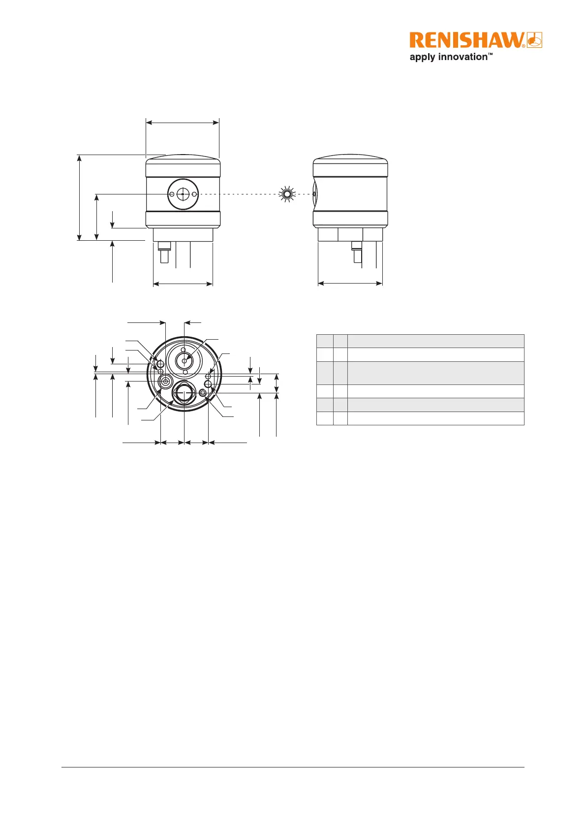
Dimensions of NC4 units
Ø30 (Ø1.18)
35 (1.38)
19 (0.75)
5.4 (0.21)
24 (0.95) A/F
7.5 (0.29)
A
E
B
B
1.0 (0.039)
4.0 (0.16)
3.0 (0.12)
C
D
9.5 (0.37)
9.5 (0.37)
F
A
7.5 (0.29)
4.0 (0.16)
1.0 (0.039)
Ø26 (Ø1.02)
Dimensions given in mm (in)
A = Mounting holes (×2) M3 × 0.5 P × 8 (0.32) deep.
B = Dowel holes (×2) Ø2 × 8 (0.32) deep.
C = Pneumatic push-t connector Ø3 (Ø.12) plastic
pipe.
D = Supply cable, Ø6 mm (Ø.24).
E = PassiveSeal vent. Do not cover
F = Blanking screw. Do not disturb.
View from bottom of
transmitter and receiver
 Loading...