3-8
NC4 non-contact tool setting system: System installation
NC4 system wiring details
The colour and intended function of each of the wires from the NC4 unit transmitter and receiver heads
are described below.
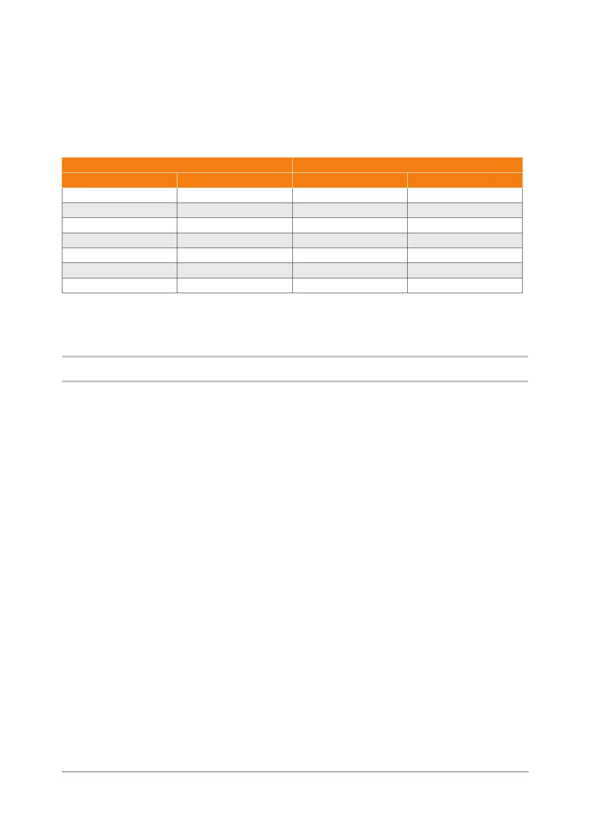
Wiring details
NC4 transmitter head NC4 receiver head
Wire colour Function Wire colour Function
Green Screen Green Screen
Black 0 V Black 0 V
Red 12 V Red 12 V
White Not used* White Analogue output 1
Blue Not used* Blue Analogue output 2
Purple Not used* Purple Set-up
Grey Status Grey Status
* As this wire is not used, ensure that the free end is correctly insulated.
Supplying electrical power to the NCi-6 interface unit
WARNING: Before switching on electrical power, ensure that the machine is safe to work on.
1. Ensure that the NCi-6 interface unit and air supplies have been connected correctly (see the table
above for further information).
2. Switch on electrical power to the NCi-6 interface unit.
3. Check that the status LEDs on the NC4 transmitter and receiver heads are lit.
What to do next
When the NCi-6 interface unit is powered up, switch on the air supply and set the correct air pressure (see
page3-9, “Setting the NC4 barrier air pressure”, for further information).
Power loss and restoration
If electrical power to the NCi-6 interface unit is lost and subsequently restored when the NC4 system is
in a normal operating mode, the NC4 system powers down and then powers up again without loss of the
original gain settings.
 Loading...