3-4
NC4 non-contact tool setting system: System installation
What to do next
After you have nished installing the air preparation pack, install the NC4 system (see page 3-4,
“Installing the NC4 system”, for further information).
Do not switch on the air supply or set the air pressure until the NC4 unit and NCi-6 interface unit have
been installed and electrical power has been supplied.
Installing the NC4 system
This procedure specically describes how to install an NC4 system with a 3-plate adjuster pack. This
procedure should also be followed for the installation of a single plate adjuster pack.
WARNING: Before starting to install the NC4 system, ensure that the machine is safe to work on. Switch
off machine power when working in the control cabinet.
NOTE: The sequence of operations required to install a separate NC4 system may differ from the
sequence described here, depending on the environment in which the system is being installed.
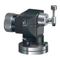
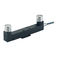
1. Find a suitable position to secure the NC4 transmitter and receiver mounting brackets. Ensure air
will be able to exit freely from the MicroHole™ in the access panels and that air will not be directed
towards an operator.
NOTE: Do not mount the system in a position where excessive quantities of swarf can build up.
2. Secure the mounting brackets to the machine.
3. Before connecting any pipe to the NC4 unit, use the air regulator to purge the pipe and remove any
debris.
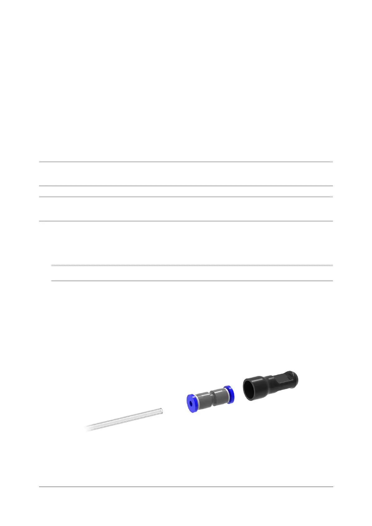
4. Connect the Ø3 mm barrier air pipe to the air inlet of the NC4 unit. Fit the Ø3 mm to Ø4 mm straight
adaptor pneumatic tting and blanking cap to the free end of the Ø3 mm air pipe.
Blanking cap
Ø3 mm to Ø4 mm
straight adaptor
Ø3 mm air pipe
(from NC4 unit)
 Loading...