70
/108
Bosch Rexroth AG CS351/CC-CS351
| 3 609 929 B45/2013-06
Product description
Motor OFF interface XDN1
Two independent motor OFF circuits are
available:
• Motor OFF circuit 1 (NH1) is implemented
via a contactor installed in the Compact
System. This separates the motor from the
servo amplifier (motor is braked).
• Motor OFF circuit 2 (NH2) prevents the
development of a motor rotating field (mo-
tor is not braked).
Both connections are bridged in the delivery
state.
Fig. 7: Delivery state with bridged motor OFF
circuits (NH1 and NH2)
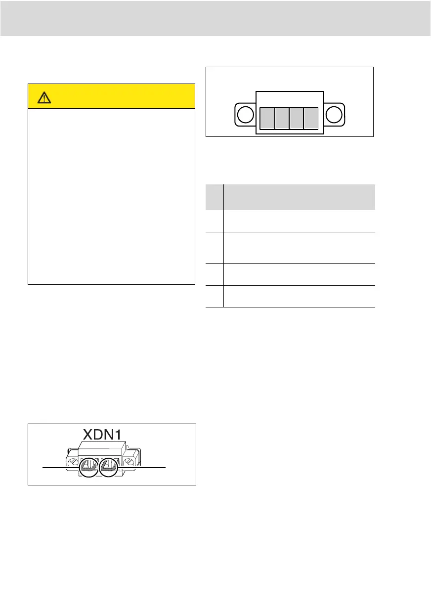
Fig. 8: XDN1
Boundary conditions:
• The maximum cable length for the motor
OFF circuit is 30 m.
• Always design the motor OFF circuits sep-
arately and with potential-free contacts. Do
not mix up the motor OFF circuits under
any circumstances.
• Both motor OFF interfaces must be led
back. If only one is used, the other one
must be provided with a wire jumper.
• If you are only using one motor OFF con-
nection option, we recommend implement-
ing the motor OFF function via motor OFF
circuit NH1 (see Fig. 9, page 72).
CAUTION
Risk of damage to persons and
property!
The emergency OFF interface is no sub-
stitute for an emergency stop facility. It
does not offer functional safety according
to
EN ISO 13849. The user is responsible
for determining the necessity of an emer-
gency OFF, its implementation, and the
risk analysis!
Make sure the emergency OFF equip-
ment is accessible and effective. Re-
lease of the emergency OFF equip-
ment may not result in an
uncontrolled system restart!
Table 5: XDN1 assignment
Pin
Signal as-
signment
Description/
function
Voltage/
current
1 VEE NH1 Motor OFF 1
supply voltage
24 V/0.3 A
2 NH1 Motor OFF 1 re-
turn (motor con-
tactor)
24 V/0.1A
3 VEE NH2 Motor OFF 2
supply voltage
24 V/0.3 A
4 NH2 Motor OFF 2 re-
turn (end step)
24 V/0.1A
CS351_zweispaltig - D.book Seite 70 Dienstag, 16. Juli 2013 12:00 12