20151763
8
Technical description of the burner
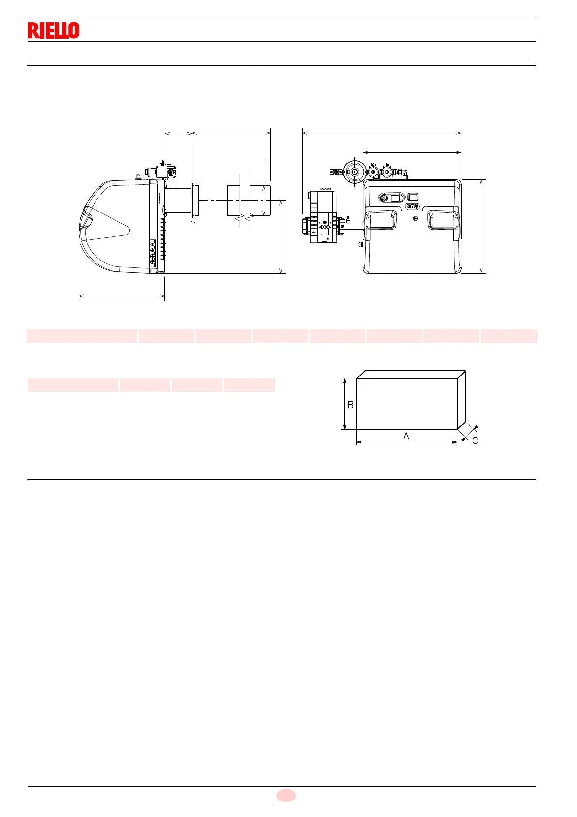
4.5 Maximum dimensions
The maximum dimensions of the burner are given in Fig. 1.
Bear in mind that, in order to inspect the combustion head, the
burner must be pulled back.
Tab. E
Tab. F
4.6 Burner equipment
Pilot gas train . . . . . . . . . . . . . . . . . . . . . . . . . . . . . . . . . . . No. 1
Flange for gas train . . . . . . . . . . . . . . . . . . . . . . . . . . . . . . No. 1
Screws to fix the flange . . . . . . . . . . . . . . . . . . . . . . . . . . . No. 4
Insulating gasket . . . . . . . . . . . . . . . . . . . . . . . . . . . . . . . . No. 1
Gas valve with flange and gas pipe . . . . . . . . . . . . . . . . . . No. 1
Instructions. . . . . . . . . . . . . . . . . . . . . . . . . . . . . . . . . . . . . No. 1
Spare parts list . . . . . . . . . . . . . . . . . . . . . . . . . . . . . . . . . . No. 1
Hardware for burner assembly:
M8 x 50 stainless steel nuts (with or without tip) . . . . . . . . No. 4
M8 x 16 zinc plated washers . . . . . . . . . . . . . . . . . . . . . . . No. 4
M8 toothed washers . . . . . . . . . . . . . . . . . . . . . . . . . . . . . No. 4
M8 zinc-plated nuts . . . . . . . . . . . . . . . . . . . . . . . . . . . . . . No. 4
Compensation pipe . . . . . . . . . . . . . . . . . . . . . . . . . . . . . . No. 1
mm H L P T TX D E
RX 500 S/PV 456 770 550 635 442 144 353
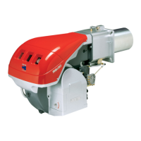
mm A B C
RX 500 S/PV 1280 564 520