19
20151763
Installation
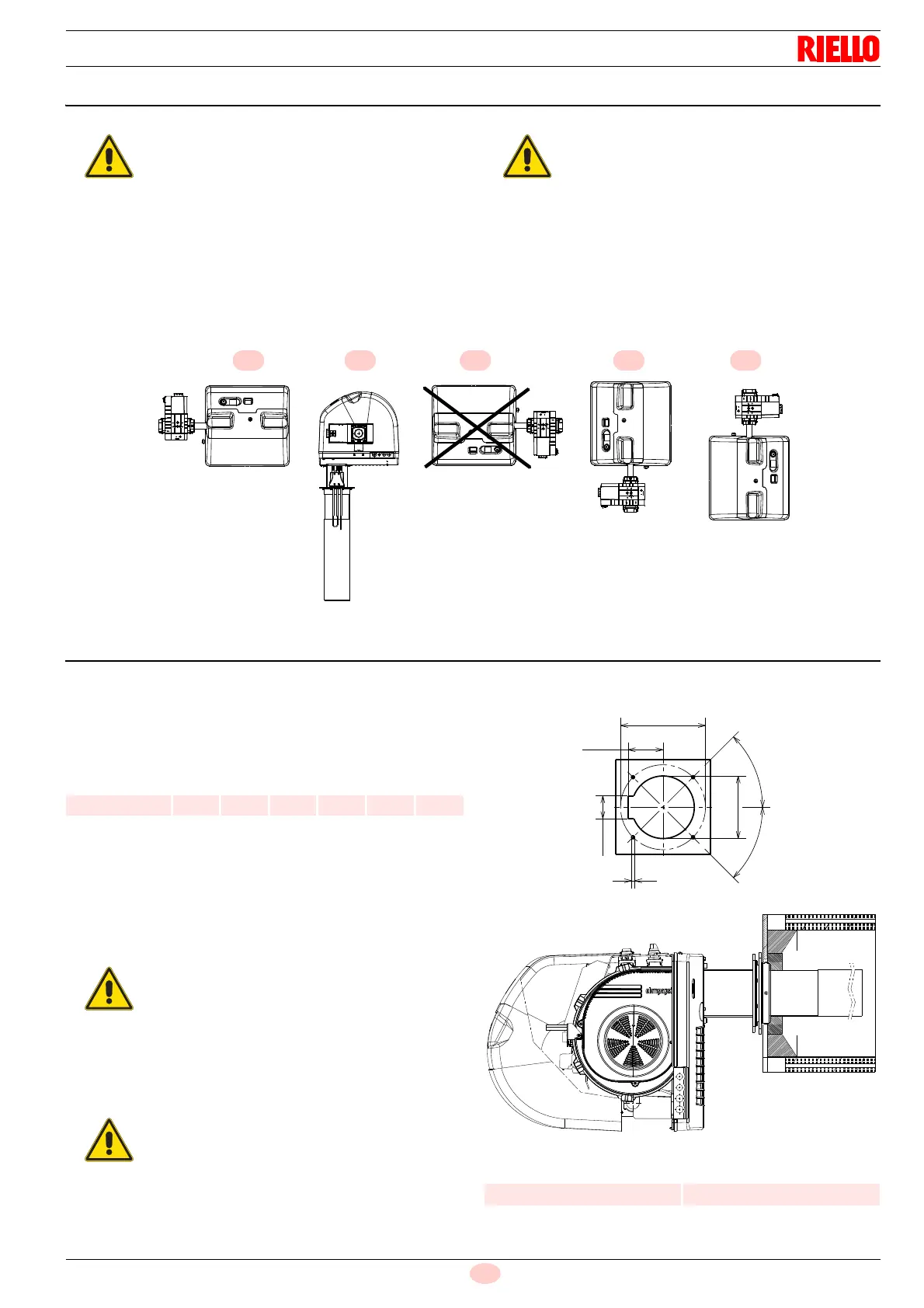
5.4 Operating position
5.5 Preparing the boiler
5.5.1 Boring the boiler plate
Pierce the closing plate of the combustion chamber, as in Fig. 13.
The position of the threaded holes can be marked using the ther-
mal insulation screen supplied with the burner.
Tab. N
5.5.2 Head length
The length of the head must be selected according to the indica-
tions provided by the manufacturer of the boiler, and in any case
the combustion area must be greater than the thickness of the
boiler door complete with refractory.
It is possible to insert a protective device made of refractory
material between the combustion head and the boiler refractory.
This protective device must allow the blast tube to be taken out
(Fig. 14).
Tab. O
The burner is designed to operate only in
positions 1, 2, 4 and 5 (Fig. 12).
Installation 1 is preferable, as it is the only
one that allows the maintenance operations
as described in this manual.
Installations 2, 4 and 5 allow operations to be
performed, but make maintenance and
inspection of the combustion head more diffi-
cult.
All the positions require the installation of the
gas valve with coils facing upwards or hori-
zontally (Fig. 12).
Any other position could compromise the cor-
rect operation of the appliance.
Installation 3 is prohibited for safety reasons.
Installation with the coils pointing downwards
is absolutely forbidden.
mm D1 W1 R DX2 DX1 W6
RX 500 S/PV 163 224 M8 100 68 45°
The burners cannot be used on flame inversion
boilers.
Do not insert the protection in line with the elec-
trode unit, as this would compromise its good op-
eration.
mm Non-combustion area
RX 500 S/PV 180
 Loading...