20041904
12
Technical description of the burner
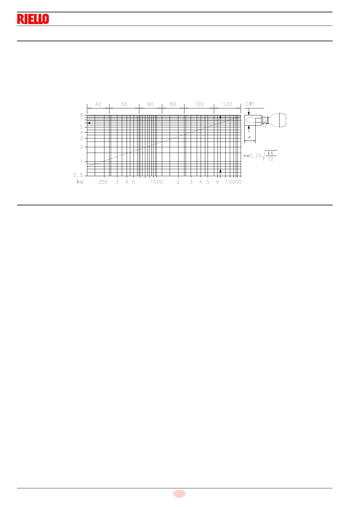
4.8 Test boiler
The burner/boiler combination does not pose any problems if the
boiler is EC approved and its combustion chamber dimensions
are similar to those indicated in the diagram (Fig. 3).
If the burner must be combined with a boiler that has not been EC
approved and/or its combustion chamber dimensions are clearly
smaller than those indicated in the diagram, consult the manufac-
turer.
The firing rates were obtained in special test boilers, according to
EN 676 regulations.
In Fig. 3 you can see the diameter and length of the test combus-
tion chamber.
Example: RS 800/E BLU
Output 7000 kW - diameter 120 cm - length 6 m.
4.9 Burner equipment
Gasket for gas train adaptor. . . . . . . . . . . . . . . . . . . . . . . . No. 1
M16 x 70 Screws to fix the gas train adaptor. . . . . . . . . . . No. 8
Thermal insulation screen . . . . . . . . . . . . . . . . . . . . . . . . . No. 1
M 18 x 60 screws to secure the burner flange
to the boiler . . . . . . . . . . . . . . . . . . . . . . . . . . . . . . . . . . . . No. 4
Pressure switch (for leak detection control). . . . . . . . . . . . No. 1
Spacers (Fig. 16 on page 21). . . . . . . . . . . . . . . . . . . . . . . No. 2
Cable grommets kit for optional electrical wiring input. . . . No. 1
M16 x 67 stud bolts to fix the gas elbow
to the pipe coupling (for RS 650-800/E BLU only) . . . . . . . No. 8
M16 nuts to fix the gas elbow
to the pipe coupling (for RS 650-800/E BLU only) . . . . . . . No. 8
Instructions. . . . . . . . . . . . . . . . . . . . . . . . . . . . . . . . . . . . . No. 1
Spare parts list . . . . . . . . . . . . . . . . . . . . . . . . . . . . . . . . . . No. 1
Fig. 3
Combustion chamber
M
D2448