19
20041904
Installation
5.4 Operating position
5.5 Removal of the locking screws from the shutter
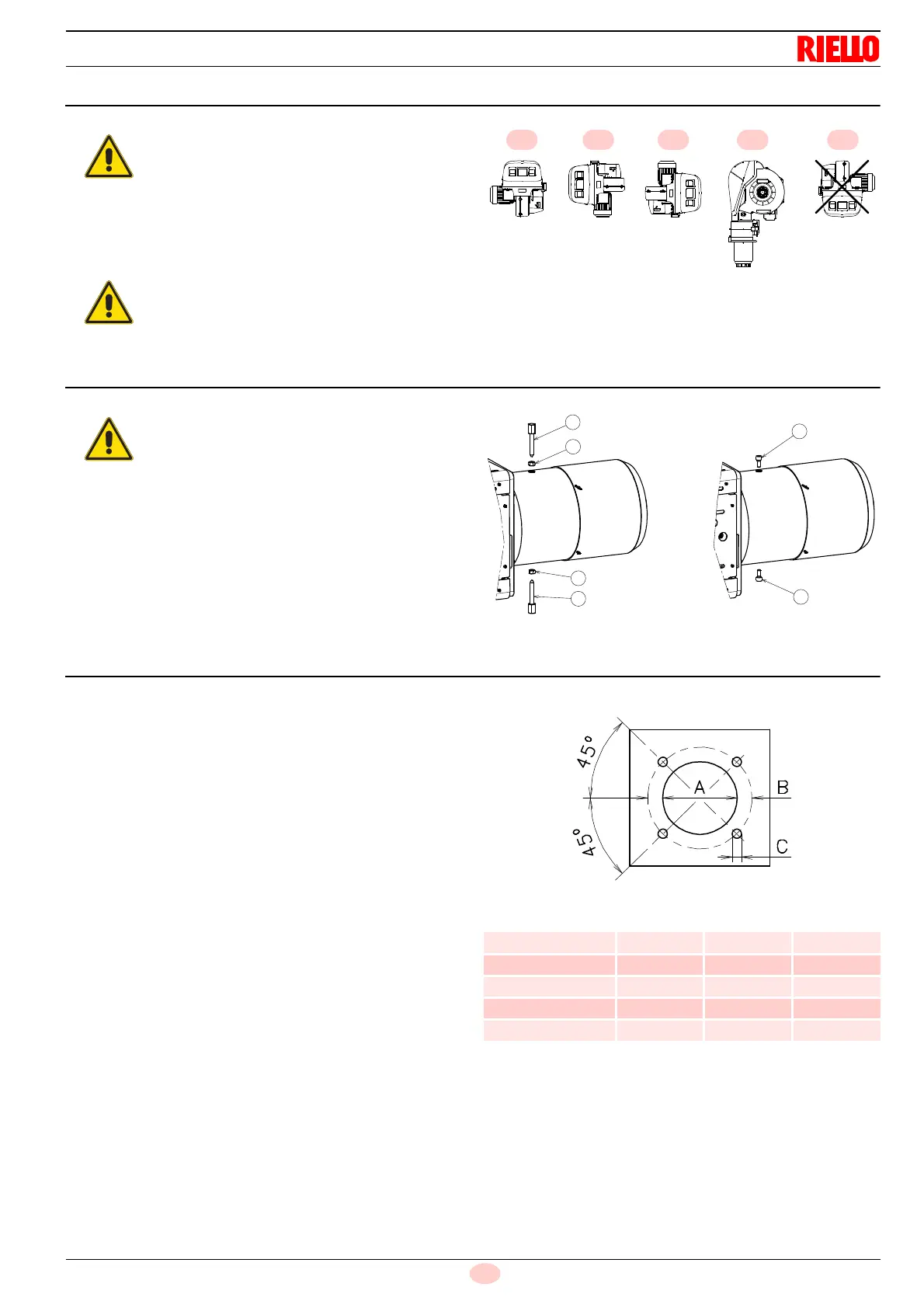
5.6 Preparing the boiler
5.6.1 Boring the boiler plate
Pierce the closing plate of the combustion chamber, as in Fig. 11.
The position of the threaded holes can be marked using the ther-
mal insulation screen supplied with the burner.
5.6.2 Blast tube length
The length of the blast tube must be selected according to the in-
dications provided by the manufacturer of the boiler, and in any
case it must be greater than the thickness of the boiler door com-
plete with its refractory.
For boilers with front flue passes 1) (Fig. 12) or flame inversion
chamber, a protection in refractory material 5) must be inserted
between the boiler fettling 2) and the blast tube 4).
This protection must not compromise the extraction of the blast
tube.
For boilers with a water-cooled frontpiece, a refractory lining 2)-
5) (Fig. 12) is not necessary, unless expressly requested by the
boiler manufacturer.
Tab. L
➤
The burner is designed to operate only in
positions
1
,
2
,
3
and
4
(Fig. 9).
➤
Installation
1
is preferable, as it is the only
one that allows the maintenance operations
as described in this manual.
➤
Installations
2
,
3
and
4
permit operation but
make maintenance and inspection of the
combustion head more difficult.
➤
Any other position could compromise the cor-
rect operation of the appliance.
➤
Installation
5
is prohibited for safety reasons.
Remove the screws and the nuts 1)-2)(Fig. 10),
before installing the burner on the boiler.
Replace them with the screws 3) M12 X 25 sup-
plied with the burner.
mm A B C
RS 300/E BLU 350 452 M18
RS 400/E BLU 350 452 M18
RS 500/E BLU 390 452 M18
RS 650/E BLU 400 495 M18
RS 800/E BLU 400 495 M18