23
20041904
Installation
5.11 Gas feeding
5.11.1 Gas feeding line
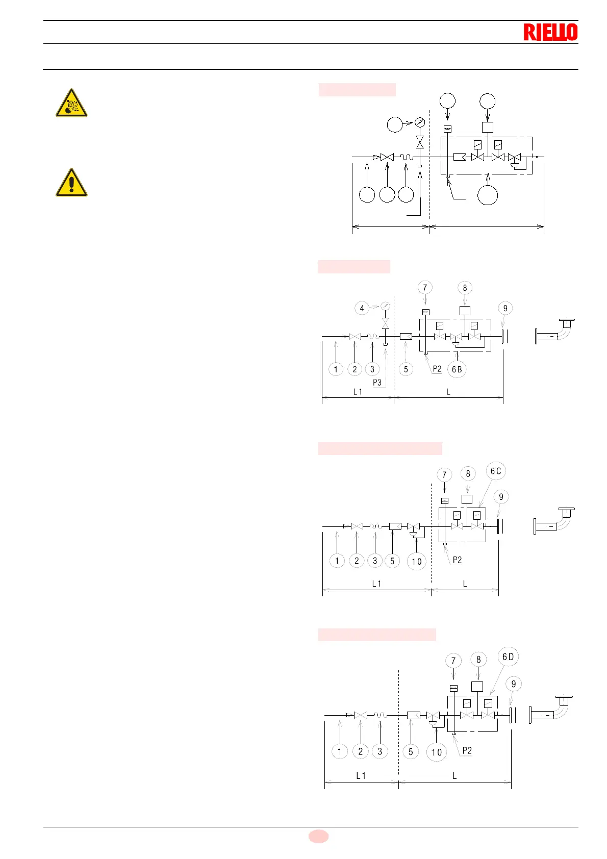
Key (Fig. 18 - Fig. 19 - Fig. 20 - Fig. 21)
1 Gas input pipe
2 Manual valve
3 Vibration damping joint
4 Pressure gauge with pushbutton cock
5 Filter
6A Includes:
– Filter
– working valve
– safety valve
– pressure adjuster
6B Includes:
– working valve
– safety valve
– pressure adjuster
6C Includes
– safety valve
– working valve
6D Includes:
– safety valve
– working valve
7 Minimum gas pressure switch
8 Leak detection device, supplied as an accessory or incorpo-
rated, based on the gas train code. In compliance with the
EN 676 standard, the leak detection control is compulsory for
burners with maximum outputs over 1200 kW.
9 Gasket, for “flanged” versions only
10 Pressure adjuster
P2 Upstream pressure of valves/adjuster
P3 Upstream pressure of the filter
L Gas train supplied separately
L1 The responsibility of the installer
Explosion danger due to fuel leaks in the pres-
ence of a flammable source.
Precautions: avoid knocking, attrition, sparks and
heat.
Make sure that the fuel interception tap is closed
before performing any operation on the burner.
The fuel supply line must be installed by qualified
personnel, in compliance with current standards
and laws.
Fig. 18
D11854
MBC “threaded”
Fig. 19
MBC “flanged”
20065706
Fig. 20
DMV “flanged or threaded”
20065609
Fig. 21
CB “flanged or threaded”
20065707