20041904
14
Technical description of the burner
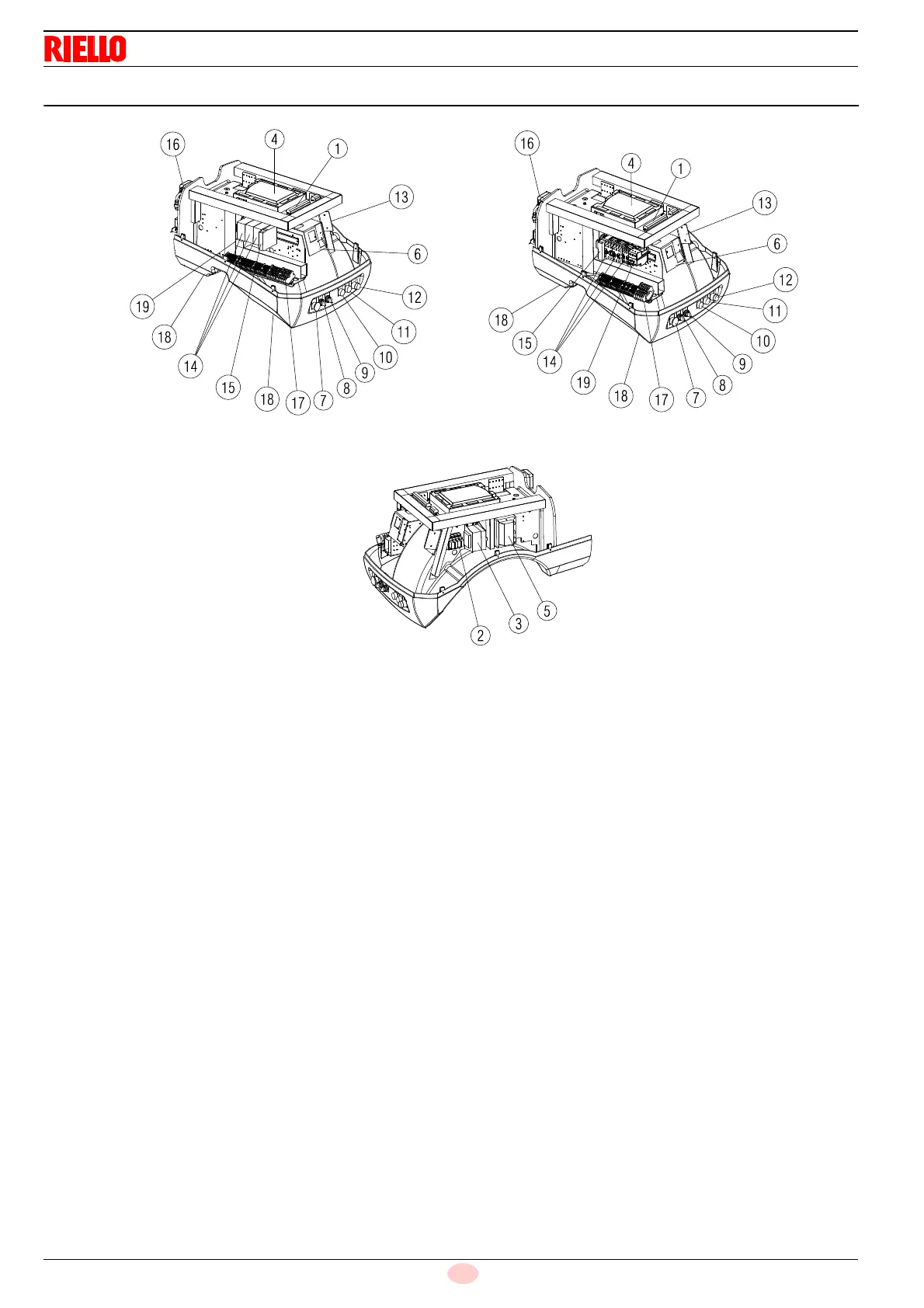
4.11 Electrical panel description
1 Terminal board for kits
2 Volt-free contacts output relay
3 Electronic cam transformer
4 Calibration device with electronic cam
5 Ignition transformer
6 Bracket for application of output power Regulator kit RWF40
7 Stop push-button
8 OFF-automatic-manual selector
9 Power increase - power reduction selector
10 Light signalling of mains live state
11 Fan motor lock-out warning lamp
12 Light signalling of burner lockout and reset switch
13 AZL kit support
14 Star-triangle starter (except for RS 300/E BLU)
15 Timer (except for RS 300/E BLU)
16 Air pressure switch
17 Main terminal supply board
18 Supply cables and external connections passage
19 Thermal relay
NOTE
Two types of burner lockout may occur:
➤ Flame control lockout: if the pilot light 12)(Fig. 5) on the
panel lights up, it indicates that the burner is in lockout.
release by pressing the pushbutton 12)(Fig. 5).
➤ Motor lockout: release by pressing the button on thermal
relay.
Fig. 5
20081364
RS 300/E BLU RS 650/E BLU
RS 800/E BLURS 400/E BLU
RS 500/E BLU