20041904
28
Start-up, calibration and operation of the burner
6.5 Combustion air adjustment
Fuel/combustion air synchronization is done with the relevant
servomotors (air and gas) by logging a calibration curve by
means of the electronic cam.
It is advisable, to reduce the loss and for a wide calibration field,
to adjust the servomotors to the maximum of the output used, the
nearest possible to the maximum opening (90°).
On the gas butterfly valve, fuel step according to the burner out-
put required, with servomotor completely open, is carried out by
the pressure stabilizer placed on the gas train.
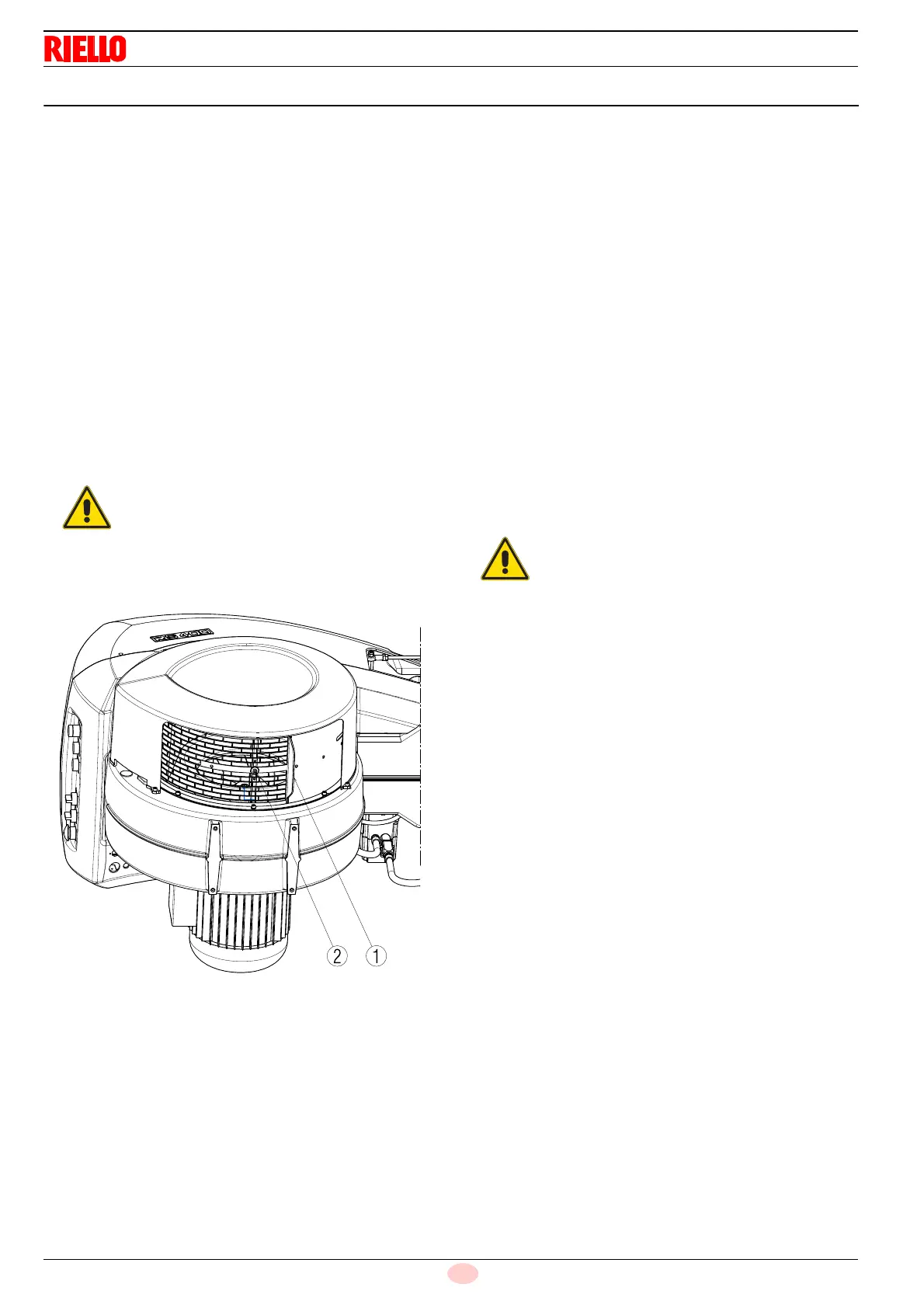
6.5.1 Air adjustment for maximum output
Excluding model RS 800/E BLU
➤
Adjust the servomotor to maximum opening (nearly 90°) so
that the air butterfly valves are entirely open;
➤
Loosen the screw 2)(Fig. 26) placed under the burner suc-
tion line and close progressively the grid 1) until the required
output is reached.
Steps in suction line are not necessary only in case in which the
burner is working at maximum of the firing rate on page 11.
6.5.2 Air/fuel adjustment and output modulation
system
The air/gas regulator and output modulation system equipping
RS/E
series burners performs a number of integrated functions to
optimise burner function, in both individual installations and in
combination with other units (e.g. double furnace boiler or multi-
ple heat generators in parallel).
The basic system functions control:
1 The dosage of the air and fuel through positioning using
direct servocommands of the relevant valves eliminating the
possible play in the calibration systems with mechanical
cam lever mechanisms, used on traditional modulating
burners.
2 The modulation of the burner output in accordance with the
load required by the system, with maintenance of the pres-
sure or temperature of the boiler at the operating values set.
3 The sequence (cascade adjustment) of more than one
boiler through the suitable connection of the various units
and the activation of the internal software of the individual
systems (option).
Further interfaces and communication functions with computers,
for remote control or integration in central supervision systems
are available on the basis of the configuration of the system.
The first start-up and curve synchronization manual is supplied
with the burner.
At request, the complete manual for the control and setting of all
parameters is available.
It is advisable to reach the maximum output re-
quired manually and, just after defining the steps
in suction line, the gas pressure and the combus-
tion head adjustment, carry out complete calibra-
tion and logging of the fuel/combustion
synchronisation curves.
The first start up and every further internal setting
operation of the adjustment system or the expan-
sion of the base functions require access by
means of password and are to be carried out by
service personnel who are especially trained for
the internal programming of the instrument and
the specific application created with this burner.