21
20041904
Installation
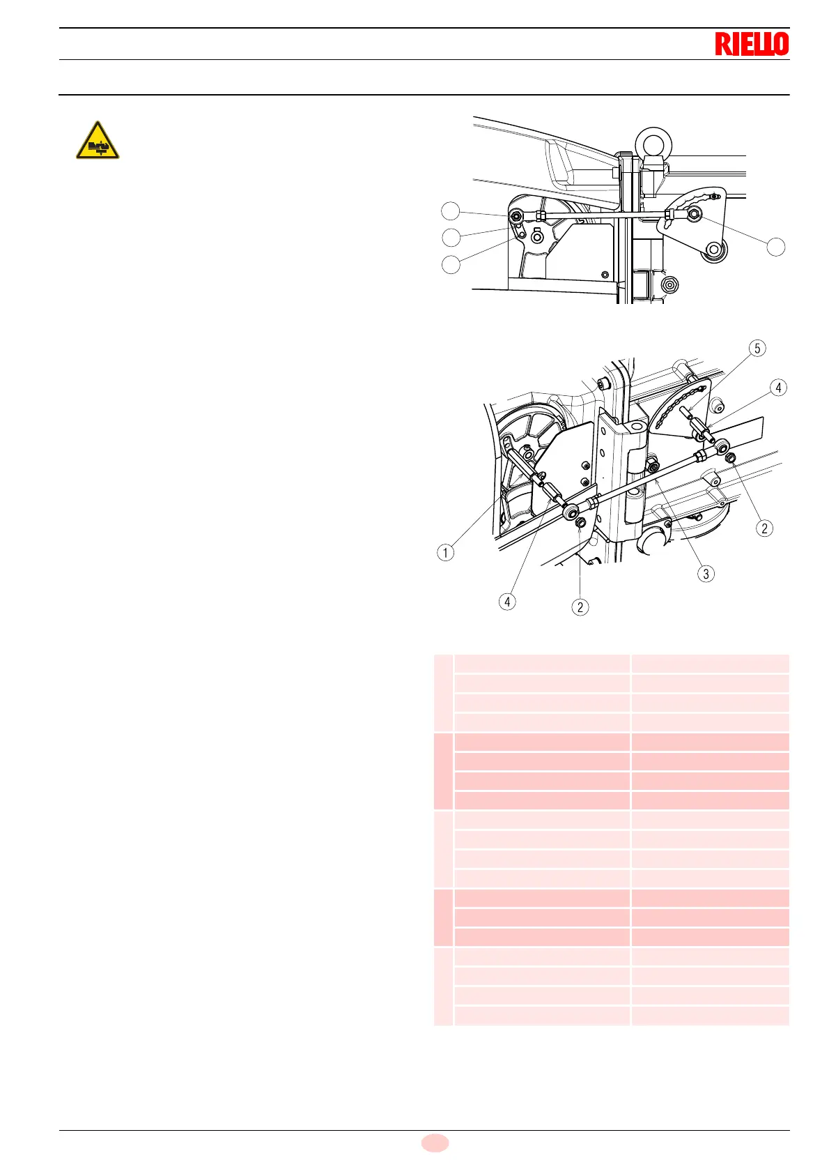
5.10 Combustion head adjustment
The air damper servomotor 4)(Fig. 4 on page 13), beyond vary-
ing the air output according to the output demand, through a lev-
erage varies the combustion head adjustment.
This system allows an optimum adjustment also at minimum fir-
ing rate.
Similarly to servomotor rotation, it is possible to vary the opening
of the combustion head moving the tie-rod on the holes (1-2-3),
(Fig. 15).
The selection of the hole (1-2-3) to be used is determined accord-
ing to the maximum output requested (Tab. M).
In the factory, the hole is adjusted for the maximum stroke
(hole 3).
In case in which, with boilers with high back pressure, also with
damper completely open, the air output is not enough, it is possi-
ble to carry out a calibration different to the one indicated by the
Tab. M, moving the tie-rod on the following higher hole, increas-
ing the opening of the combustion head and the air output.
If, for combustion reasons, it is necessary to move the spacer
1)(Fig. 16) onto the 1st and 2nd hole of the gear, while the hinge
is positioned to the right, the spacers 4) supplied as standard
must be mounted.
Proceed as follows:
➤
after you have unscrewed the nuts 2)(Fig. 16), remove the
tie-rod 3), unscrew the spacer 1) and position it in the appro-
priate hole;
➤
tighten the spacers 4) to spacer 1) and screw 5) respec-
tively;
➤
mount the tie-rod 3) and the nuts 2) again.
Tab. M
Pay attention to moving parts.
Danger of crushing of limbs!
Output
(kW) No. Hole
RS 300/E
1200 1
2200 2
2800 3
3200 3
RS 400/E
1800 1
3400 2
4000 3
4500 3
RS 500/E
1000 1
2500 2
3500 3
5200 3
RS 650/E
1400 2
4700 3
6500 3
RS 800/E
1800 1
4000 2
6000 3
8100 3