29
20041904
Start-up, calibration and operation of the burner
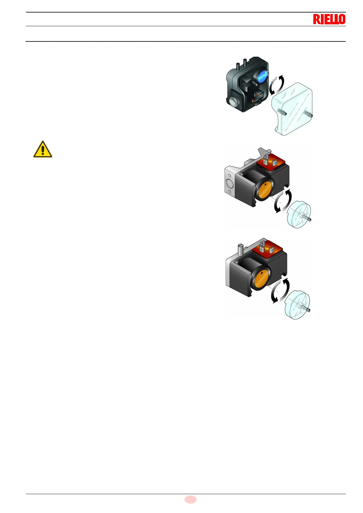
6.6 Pressure switch adjustment
6.6.1 Air pressure switch - check CO
Adjust the air pressure switch (Fig. 27) after performing all other
burner adjustments with the air pressure switch set to the start of
the scale.
With the burner operating at MIN output, increase adjustment
pressure by slowly turning the relative knob clockwise until the
burner locks out.
Then turn the knob anticlockwise by about 20% of the set point
and repeat burner start-up to ensure it is correct.
If the burner locks out again, turn the knob anticlockwise a little
bit more.
On RS
300-400-500
/E BLU burners the air pressure switch is fit-
ted in a “differential” mode, that is, with two pipes connected to
the specific pressure test points “+” and “-” 22)-23 Fig. 4 on
page 13).
On RS
650-800
/E BLU burners the air pressure switch is fitted in
an “absolute” mode, that is, connected only to the pressure test
point “+” 22) Fig. 4 on page 13).
6.6.2 Maximum gas pressure switch
Adjust the maximum gas pressure switch (Fig. 28) after perform-
ing all other burner adjustments with the maximum gas pressure
switch set to the end of the scale.
With the burner operating at maximum output, lower adjustment
pressure by slowly turning the relative knob anticlockwise until
the burner locks out.
Turn the knob clockwise by 2 mbar and repeat the start-up of the
burner.
If the burner locks out again, turn the knob clockwise again by 1
mbar.
6.6.3 Minimum gas pressure switch
Adjust the minimum gas pressure switch (Fig. 29) after perform-
ing all the other burner adjustments with the pressure switch set
to the start of the scale.
With the burner operating at maximum output, increase adjust-
ment pressure by slowly turning the relative knob clockwise until
the burner locks out.
Then turn the knob anticlockwise by 2 mbar and repeat burner
start-up to ensure it is uniform.
If the burner locks out again, turn the knob anticlockwise again by
1 mbar.
In conformity with the standard, the air pressure
switch must prevent the air pressure falling below
80% of the adjusted value and the CO in the flue
gases exceeding 1% (10,000 ppm).
To check this, insert a combustion analyser into
the chimney, slowly close the fan suction inlet (for
example with cardboard) and check that the burn-
er locks out, before the CO in the fumes exceeds
1%.